BGA 416 E6327 Infineon Technologies, BGA 416 E6327 Datasheet - Page 5
BGA 416 E6327
Manufacturer Part Number
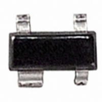
BGA 416 E6327
Description
AMP RF CASCODE 6V 20MA SOT-143
Manufacturer
Infineon Technologies
Type
General Purpose Amplifierr
Datasheet
1.BGA_416_E6327.pdf
(8 pages)
Specifications of BGA 416 E6327
Noise Figure
1.6dB
Current - Supply
5.5mA
Frequency
100MHz ~ 3GHz
Gain
11dB
P1db
-3dBm
Package / Case
SOT-143, SOT-143B, TO-253AA
Rf Type
Cellular, GSM, CDMA, TDMA, UMTS
Test Frequency
1.8GHz
Voltage - Supply
2.5V ~ 5V
Supply Current
5.5 mA
Maximum Power Dissipation
100 mW
Maximum Operating Temperature
+ 150 C
Mounting Style
SMD/SMT
Minimum Operating Temperature
- 65 C
Number Of Channels
1 Channel
Manufacturer's Type
MMIC Amplifier
Operating Supply Voltage (min)
2.5V
Operating Supply Voltage (typ)
3V
Operating Supply Voltage (max)
5V
Package Type
SOT-143
Mounting
Surface Mount
Pin Count
3 +Tab
Noise Figure (typ)
1.6@1800MHzdB
Operating Temp Range
-65C to 150C
Operating Temperature Classification
Military
Lead Free Status / RoHS Status
Lead free / RoHS Compliant
Lead Free Status / RoHS Status
Lead free / RoHS Compliant, Lead free / RoHS Compliant
Other names
BGA 416 E6327
BGA416E6327INTR
BGA416E6327XT
SP000013607
BGA416E6327INTR
BGA416E6327XT
SP000013607


Maximum Ratings
Table 1
Parameter
Voltage at pin RFout
Device current
Current into pin RFin
Input power
Total power dissipation,
Junction temperature
Ambient temperature range
Storage temperature range
1) Device current is equal to current into pin RFout
2)
Note: All Voltages refer to GND-Node
Thermal resistance
Table 2
Parameter
Junction - soldering point
1) For calculation of
2
Electrical characteristics at
V
Table 3
Parameter
Maximum available power gain
Insertion power gain
Reverse isolation
Noise figure (
Output power at 1 dB gain
compression (
Output third order intercept point
(
Device current
Data Sheet
Z
CC
S
T
=
= 3 V, unless otherwise specified
S
Z
is measured on the ground lead at the soldering point
L
= 50 )
Maximum ratings
Thermal resistance
Electrical Characteristics
Electrical Characteristics
Z
Z
1)
S
S
= 50
=
Z
R
L
thJA
= 50 )
please refer to Application Note Thermal Resistance
T
1)
S
< 123°C
T
A
= 25 °C (measured in test circuit specified in
2)
Symbol
G
|S
|S
F
P
OIP
I
D
Symbol
V
I
I
P
P
T
T
T
Symbol
R
50
-1dB
MA
21
12
D
in
J
A
STG
OUT
in
tot
thJS
|
|
2
3
Min.
5
Typ.
23
14
17
11
60
40
1.2
1.6
-3
-3
14
14
5.5
Values
Limit Value
6
20
0.5
8
100
150
-65... 150
-65... 150
Value
270
Max.
Figure
2)
Electrical Characteristics
Unit
dB
dB
dB
dB
dB
dB
dB
dB
dBm
dBm
dBm
dBm
mA
Unit
V
mA
mA
dBm
mW
°C
°C
°C
Unit
K/W
Rev. 2.1, 2008-04-21
Note /
Test Condition
f
f
f
f
f
f
f
f
f
f
f
f
= 0.9 GHz
= 1.8 GHz
= 0.9 GHz
= 1.8 GHz
= 0.9 GHz
= 1.8 GHz
= 0.9 GHz
= 1.8 GHz
= 0.9 GHz
= 1.8 GHz
= 0.9 GHz
= 1.8 GHz
BGA416
Related parts for BGA 416 E6327
Image
Part Number
Description
Manufacturer
Datasheet
Request
R

Part Number:
Description:
BGA 416/32 BIT FLASH
Manufacturer:
Infineon Technologies AG
Datasheet:

Part Number:
Description:
Manufacturer:
Altera Corporation
Datasheet:


Part Number:
Description:
bga 48/ASYNCHRONOUS SRAM's 256K x 16 (4 Meg) A Revision
Manufacturer:
GSI Technology
Part Number:
Description:
BGA 48/ASYNCHRONOUS SRAM's 256K x 16 (4 Meg) A Revision
Manufacturer:
GSI Technology
Datasheet:
Part Number:
Description:
BGA 165/I�/144Mb SigmaQuad-II+Burst of 4 SRAM
Manufacturer:
GSI Technology
Datasheet:
Part Number:
Description:
BGA 165/1M x 18 (18 Meg) Burst of 4
Manufacturer:
GSI Technology
Datasheet:
Part Number:
Description:
BGA 165/1M x 18 (18 Meg) Burst of 4
Manufacturer:
GSI Technology
Datasheet:
Part Number:
Description:
BGA 165/SYNCHRONOUS SRAM's 1M x 18 (18 Meg) Burst of 4
Manufacturer:
GSI Technology
Datasheet:
Part Number:
Description:
BGA 119/I�/SYNCHRONOUS SRAM's/128K x 36 (4 Meg) Synch Burst A Rev
Manufacturer:
GSI Technology
Datasheet:
Part Number:
Description:
BGA 165/SYNCHRONOUS SRAM's 4M x 18 (72 Meg) Burst of 4
Manufacturer:
GSI Technology
Datasheet: