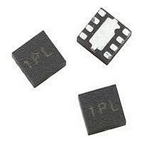
MGA-545P8-TR1 Avago Technologies US Inc., MGA-545P8-TR1 Datasheet - Page 3

MGA-545P8-TR1
Manufacturer Part Number
MGA-545P8-TR1
Description
IC AMP RFIC GAAS 5.8GHZ 8-LPCC
Manufacturer
Avago Technologies US Inc.
Datasheet
1.MGA-545P8-TR2.pdf
(10 pages)
Specifications of MGA-545P8-TR1
Gain
11.5dB
Rf Type
WLL, WLAN
Current - Supply
135mA
Frequency
50MHz ~ 7GHz
Noise Figure
2.9dB
P1db
21.3dBm
Package / Case
8-LPCC
Test Frequency
3GHz
Voltage - Supply
3.3V
Frequency Range
50MHz To 7GHz
Noise Figure Typ
34dB
Power Dissipation Pd
800mW
Supply Current
135mA
Supply Voltage Range
3.3V
Lead Free Status / RoHS Status
Lead free / RoHS Compliant
Available stocks
Company
Part Number
Manufacturer
Quantity
Price
Company:
Part Number:
MGA-545P8-TR1
Manufacturer:
AVAGO
Quantity:
3 000
Part Number:
MGA-545P8-TR1
Manufacturer:
AVAGO/安华高
Quantity:
20 000
Company:
Part Number:
MGA-545P8-TR1G
Manufacturer:
AVAGO
Quantity:
10 000
3
MGA-545P8 Electrical Specifications
T
Symbol
Gtest_sat
Gtest_ss
Psat
Ids_sat
Idss
P1dB
PAE
OIP3
EVM
NF
Notes:
1. Measurements made on a fixed tuned production test board (figure 1), which was optimized for gain and saturated power. Excess circuit losses had
2. Measurement was taken on demo board at which it was tuned for maximum gain and saturated power. Refer to application note.
3. Measurement was done in a 50
4. Power Added Efficiency at Psat is calculated using the following formula:
c
been de-embedded from actual measurement. Typical data based on at least 500 parts sample size from 3 wafer lots. Future wafers allocated to this
product may have nominal values anywhere within the upper and lower spec limits.
stub tuners.
= 25˚C, V
d
Parameter and Test Condition
Gain in test circuit at saturation
For all frequencies refer to note [3]
unless noted otherwise
Gain in test circuit at small signal
For all frequencies refer to note [3]
unless noted otherwise
Pout at 2.5 dB gain compression
Drain Current at saturation
Drain Current at small signal
Output Power at 1 dB compression point
For all frequencies refer to note [3]
unless noted otherwise
Power Added Efficiency at Psat
For all frequencies refer to note [3]
unless noted otherwise
Output Third Order Intercept Point [2.7 V]
Error Vector Magnitude
Pout = 16 dBm; 54 Mbps data rate
Noise Figure
For all frequencies refer to note [3]
unless noted otherwise.
= 3.3 V, unless otherwise noted
microstrip line, which was tuned for maximum gain and saturated power for each frequency with external double
[4]
f = 1.0 GHz
f = 2.0 GHz
f = 3.0 GHz
f = 4.0 GHz
f = 5.0 GHz
f = 5.825 GHz
f = 6.0 GHz
f = 1.0 GHz
f = 2.0 GHz
f = 3.0 GHz
f = 4.0 GHz
f = 5.0 GHz
f = 5.825 GHz
f = 6.0 GHz
f = 5.825 GHz
f = 5.825 GHz
f = 5.825 GHz
f = 1.0 GHz
f = 2.0 GHz
f = 3.0 GHz
f = 4.0 GH
f = 5.0 GHz
f = 5.825 GHz
f = 6.0 GHz
f = 1.0 GHz
f = 2.0 GHz
f = 3.0 GHz
f = 4.0 GHz
f = 5.0 GHz
f = 5.825 GHz
f = 6.0 GHz
f = 5.725 GHz
f = 5.725 GHz
f = 1.0 GHz
f = 2.0 GHz
f = 3.0 GHz
f = 4.0 GHz
f = 5.0 GHz
f = 5.825 GHz
f = 6.0 GHz
pa
=
Pout – Pin
Vdd x Id
[1]
[1]
[1]
[1]
[1]
[2]
[1]
[1]
[2]
[2]
Pout = Psat in watts
Pin = Input drive power in watts
Vdd = 3.3 V
Id = Ids_sat in Ampere
Units
dB
dB
dBm
mA
mA
dBm
%
dBm
%
dB
Min.
8.5
10.5
21.5
80
110
40
31
Typ.
20.0
16.3
13.4
11.6
10.05
9.5
8.7
22.4
18.6
15.9
13.5
12
11.5
11.3
22
92
127
21.5
21.7
21.3
21.8
21.2
21.0
20.6
46.3
46.0
48
44
45
46
47
34
5.6
2.6
2.7
2.9
3.3
3.6
4.4
5.2
Max.
10.5
13.8
–
115
145
–


