A6250 Antenova, A6250 Datasheet - Page 7
A6250
Manufacturer Part Number
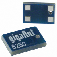
A6250
Description
ANTENNA CHIP 2.4GHZ SMD RIGHT FD
Manufacturer
Antenova
Series
Impexar
Specifications of A6250
Antenna Type
Chip
Number Of Bands
1
Frequency
2.4GHz ~ 2.5GHz
Vswr
1.9
Gain
0dBi
Termination
Surface Mount
Mounting Type
Surface Mount
Height (max)
0.04" (1.25mm)
Technology Type
Internal SMD Chip Antenna
Termination Style
SMD/SMT
Dimensions
6.1 mm L x 3.9 mm W x 1.1 mm H
Mounting Style
SMD/SMT
Lead Free Status / RoHS Status
Lead free / RoHS Compliant
Other names
3030A6250-01
627-1014-2
627-1014-2
Available stocks
Company
Part Number
Manufacturer
Quantity
Price

Part Number:
A6250
Manufacturer:
AIT-IC
Quantity:
20 000
Company:
Part Number:
A62500116W
Manufacturer:
AD
Quantity:
6 226
Company:
Part Number:
A6250016W
Manufacturer:
CY
Quantity:
2 761
Part Number:
A6250E3R-15
Manufacturer:
AIT-IC
Quantity:
20 000
Part Number:
A6250E3R-18
Manufacturer:
AIT-IC
Quantity:
20 000
Part Number:
A6250E3R-25
Manufacturer:
AIT-IC
Quantity:
20 000
Part Number:
A6250E3R-28
Manufacturer:
AIT-IC
Quantity:
20 000
Company:
Part Number:
A6250E3R-33
Manufacturer:
MAXIM
Quantity:
1 000


Impexa 2.4 GHz SMD Antenna
Part No. A6150 / A6250
In addition to the matching circuit, a separate DC blocking capacitor will also be required
between the radio and the antenna matching circuit.
Note: The component values for the matching circuit will vary depending on the size of
the PCB and surrounding components. The impedance of the antenna should be measured
before selecting suitable matching components. Antenova offers this service on request.
Contact
info@antenova.com
for further information.
10-3 Antenna placement
Antenova strongly recommends placing the antenna near the edge of the board. Maximum
antenna performance is achieved by placing the antenna towards one of the corners of the
PCB.
Additional ground and components near the antenna should be at a distance of at least 2 mm.
Where possible the antenna should be clear of ground from both sides, although the antenna
can work well with a minimum clearance of D ≥ 2 mm as shown in the drawing above.
Integrated Antenna and RF Solutions
7
Product Specification AE040034-I
Related parts for A6250
Image
Part Number
Description
Manufacturer
Datasheet
Request
R

Part Number:
Description:
ANTENNA CHIP 2.4GHZ SMD
Manufacturer:
Antenova
Datasheet:

Part Number:
Description:
ANTENNA FUSCA 2.4GHZ SMD
Manufacturer:
Antenova
Datasheet:

Part Number:
Description:
ANTENNA CHIP 2.4GHZ SMD RIGHT FD
Manufacturer:
Antenova
Datasheet:

Part Number:
Description:
ANTENNA CHIP 2.4GHZ SMD LEFT FD
Manufacturer:
Antenova
Datasheet:

Part Number:
Description:
ANTENNA MIXTUS 2.4/5GHZ SMD
Manufacturer:
Antenova
Datasheet:

Part Number:
Description:
ANTENNA CHIP 2.4GHZ SMD
Manufacturer:
Antenova
Datasheet:

Part Number:
Description:
ANTENNA BREVIS GPS 1575MHZ SMD
Manufacturer:
Antenova
Datasheet:

Part Number:
Description:
ANTENNA CALVUS 824-960MHZ SMD
Manufacturer:
Antenova
Datasheet:

Part Number:
Description:
ANTENNA GPS 1575MHZ SMD
Manufacturer:
Antenova
Datasheet:

Part Number:
Description:
ANTENNA 2.4GHZ SNAP-IN 0.8MM PCB
Manufacturer:
Antenova
Datasheet:

Part Number:
Description:
ANTENNA 2.4GHZ W/SMA
Manufacturer:
Antenova
Datasheet:

Part Number:
Description:
ANTENNA CHIP 2.4GHZ SMD LEFT FD
Manufacturer:
Antenova
Datasheet:

Part Number:
Description:
ANTENNA REFLEXUS 824-960MHZ SMD
Manufacturer:
Antenova
Datasheet:
Part Number:
Description:
ANTENNA 2.4GHZ W/REV THREAD SMA
Manufacturer:
Antenova
Datasheet:
Part Number:
Description:
ANTENNA CHIP 2.4GHZ SMD
Manufacturer:
Antenova
Datasheet: