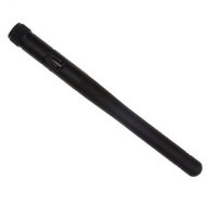
RN-SMA4-RP Roving Networks Inc, RN-SMA4-RP Datasheet - Page 6

RN-SMA4-RP
Manufacturer Part Number
RN-SMA4-RP
Description
ANTENNA 2.4GHZ 4 INCH W/RPSMA
Manufacturer
Roving Networks Inc
Datasheet
1.RN-UFL-SMA6.pdf
(8 pages)
Specifications of RN-SMA4-RP
Antenna Type
Whip: 1/4 Wave, Right Angle, Fixed
Number Of Bands
1
Frequency
2.45GHz
Vswr
1.9
Gain
2.2dBi
Termination
RP-SMA
Mounting Type
Connector
Height (max)
4.44" (113mm)
Dimensions
26.6 mm L x 51.2 mm W x 12.8 mm H
Frequency Range
2402 MHz to 2480 MHz
Mounting Style
Through Hole
Operating Temperature Range
- 30 C to + 85 C
Technology Type
Wifi Antenna
Termination Style
U.FL
Lead Free Status / RoHS Status
Lead free / RoHS Compliant
Lead Free Status / RoHS Status
Lead free / RoHS Compliant, Lead free / RoHS Compliant
Other names
740-1033
Design Concerns
1. Minimizing Radio interference. When integrating the RN-134 into your system, make sure the area around the
2. U.FL connector. Use Hirose U.FL connector U.FL-R-SMT to for connecting external antennas. See Roving
3. Powering the module. The RN-134 can be powered from the RS232 header, the UART interface or the power
4. Sensor Interfaces. Inputs must not exceed 1.2V. Sensitivity saturates at 400 mV. It is recommended that you
5. Adhoc and Restoring Factory Settings. Jumper 1 on the jumper header is connected to PIO9. When this
chip antenna that overhangs the PCB is away from any metal enclosure. If this is not possible use the on board
U.FL jack with a U.FL to SMA cable to connect an external antenna. To switch between the chip and external
antenna use the set wlan antenna <num> command where 0 = chip and 1 = U.FL.
Networks U.FL to SMA cable. Part number: RN-UFL-SMA6
connector. You should only provide power on one of the three interfaces.
If powered from the RS232 header, apply 3 to 12 VDC on pin 9 and ground to pin 5 of the RS232 header.
If powered from the UART interface, apply 3.3 VDC on pin 1 and ground on pin 2 of the UART interface.
If powered from the power connector, apply 3 to 12 VDC
use the Sensor power output to drive any analog devices that are attached to the sensor pins.
Note the exception to this is Sensor pins 2 and 3. These have a resistor network in front of sensors 4 and 5
respectfully so they can be drive with up to 5 VDC.
jumper is in place the module will power up in adhoc mode. . If the jump is then toggled 5 times, the initial factory
default configuration will be RESTORED. This is useful for cases where the module is mis-configured and is no
long responding.
www.rovingnetworks.com
809 University Avenue
•
Los Gatos, CA 95032
~ page 6 ~
•
Tel (408) 395-6539
• info@RovingNetworks.com
rn-134-ds v1.1 12/14/2009
RN-134


