AD8314ACP-REEL7 Analog Devices Inc, AD8314ACP-REEL7 Datasheet - Page 2
AD8314ACP-REEL7
Manufacturer Part Number
AD8314ACP-REEL7
Description
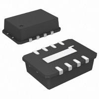
IC RF DETECTOR\CTRLR 8-LFCSP T/R
Manufacturer
Analog Devices Inc
Datasheet
1.AD8314ACPZ-RL7.pdf
(20 pages)
Specifications of AD8314ACP-REEL7
Rohs Status
RoHS non-compliant
Frequency
100MHz ~ 2.7GHz
Rf Type
Cellular, GSM, TDMA, CDMA
Input Range
-45dBm ~ 0dBm
Voltage - Supply
2.7 V ~ 5.5 V
Current - Supply
5.7mA
Package / Case
8-VFDFN, CSP Exposed Pad
Accuracy
-
Available stocks
Company
Part Number
Manufacturer
Quantity
Price
Company:

Part Number:
AD8314ACP-REEL7
Manufacturer:
NEC
Quantity:
2 122
Part Number:
AD8314ACP-REEL7
Manufacturer:
ADI/亚德诺
Quantity:
20 000


AD8314
TABLE OF CONTENTS
Features .............................................................................................. 1
Applications....................................................................................... 1
General Description ......................................................................... 1
Functional Block Diagram .............................................................. 1
Revision History ............................................................................... 2
Specifications..................................................................................... 3
Absolute Maximum Ratings............................................................ 4
Pin Configurations and Function Descriptions............................ 5
Typical Performance Characteristics ............................................. 6
Theory of Operation ...................................................................... 10
Applications..................................................................................... 12
REVISION HISTORY
5/06—Rev. A to Rev. B
Updated Format..................................................................Universal
Changes to General Description .................................................... 1
Changes to Table 1............................................................................ 3
Changes to Table 2............................................................................ 4
Inserted Figure 3; Renumbered Sequentially................................ 5
Changes to Figure 4, Figure 5, Figure 6, Figure 7,
and Figure 8 ...................................................................................... 6
Changes to Figure 9, Figure 10, and Figure 12 ............................. 7
Changes to Figure 37...................................................................... 14
Changes to Table 5.......................................................................... 15
Changes to Figure 39...................................................................... 16
Changes to Table 7.......................................................................... 19
Updated Outline Dimensions ....................................................... 20
Changes to Ordering Guide .......................................................... 20
ESD Caution.................................................................................. 4
Inverted Output .......................................................................... 11
Basic Connections ...................................................................... 12
Transfer Function in Terms of Slope and Intercept ............... 12
Rev. B | Page 2 of 20
Outline Dimensions ....................................................................... 20
3/02—Rev. 0 to Rev. A
Edit to Product Description.............................................................1
Edit to Specifications.........................................................................2
Edit to Ordering Guide ....................................................................3
Edit to TPC 1......................................................................................4
New Section (Operation at 2.7 GHz) Added.............................. 14
Addition of New Figures 14 and 15 ............................................. 14
Changes to Evaluation Board Section.......................................... 14
Addition of Chip Scale Package.................................................... 16
dBV vs. dBm ............................................................................... 13
Filter Capacitor ........................................................................... 13
Operating in Controller Mode ................................................. 13
Power-On and Enable Glitch .................................................... 14
Input Coupling Options ............................................................ 14
Increasing the Logarithmic Slope in Measurement Mode ... 15
Effect of Waveform Type on Intercept .................................... 15
Mobile Handset Power Control Examples.............................. 16
Operation at 2.7 GHz................................................................. 18
Using the LFCSP Package.......................................................... 18
Evaluation Board ........................................................................ 18
Ordering Guide .......................................................................... 20
Related parts for AD8314ACP-REEL7
Image
Part Number
Description
Manufacturer
Datasheet
Request
R

Part Number:
Description:
IC RF DETECTOR\CTRLR 8-LFCSP T/R
Manufacturer:
Analog Devices Inc
Datasheet:

Part Number:
Description:
100 MHz to 2.7 GHz, 45 dB RF Detector/Controller
Manufacturer:
Analog Devices
Datasheet:
Part Number:
Description:
100 MHz-2500 MHz 45 dB RF Detector/Controller
Manufacturer:
Analog Devices

Part Number:
Description:
±1.7g Dual-Axis IMEMS Accelerometer Evaluation Board
Manufacturer:
Analog Devices Inc
Datasheet:
Part Number:
Description:
Inertial Sensor Evaluation System
Manufacturer:
Analog Devices Inc
Datasheet:
Part Number:
Description:
Manufacturer:
Analog Devices Inc
Datasheet:
Part Number:
Description:
Manufacturer:
Analog Devices Inc
Datasheet:
Part Number:
Description:
Manufacturer:
Analog Devices Inc
Datasheet:
Part Number:
Description:
Manufacturer:
Analog Devices Inc
Datasheet:
Part Number:
Description:
Manufacturer:
Analog Devices Inc
Datasheet:
Part Number:
Description:
Manufacturer:
Analog Devices Inc
Datasheet:
Part Number:
Description:
Manufacturer:
Analog Devices Inc
Datasheet:
Part Number:
Description:
Manufacturer:
Analog Devices Inc
Datasheet: