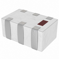
2450DP15E5400E Johanson Technology Inc, 2450DP15E5400E Datasheet - Page 21

2450DP15E5400E
Manufacturer Part Number
2450DP15E5400E
Description
DIPLEXER LPF/BPF 2.45/5.4GHZ
Manufacturer
Johanson Technology Inc
Specifications of 2450DP15E5400E
Frequency Bands (low / High)
2.4GHz ~ 2.5GHz / 4.9GHz ~ 5.9GHz
Low Band Attenuation (min / Max Db)
20.00dB / 0.70dB
High Band Attenuation (min / Max Db)
17.00dB / 1.60dB
Return Loss (low Band / High Band)
9.5dB / 9.5dB
Mounting Type
Surface Mount
Package / Case
1206 (3216 Metric)
Return Loss
9.5dB
Bandpass Insertion Loss Max
1.6dB
Attenuation @ Reject Band Min
17dB
Termination Type
SMD
Rohs Compliant
Yes
Capacitance
0µF
Lead Free Status / RoHS Status
Lead free by exemption / RoHS Compliant
Other names
2450DP15E5400
2450DP15E5400
2450DP15E5400
P
EIA SIZE (mm)
H
RF W
M
DEVICE
Example Part Number:
L-07W4N3SV4T is: 0402 Wirewound, 4.3 nanohenry, +/- 0.3 nH tolerance, Ni / Au termination, No Marking, Paper tape on a 7” reel.
* See selection chart on the following pages for available tolerances of each value.
Inductor
L
0402 (1005)
0603 (1608)
0805 (2012)
RODUCT
OW TO
L-
ECHANICAL
W
IREWOUND
O
07 = 0402
14 = 0603
15 = 0805
R
SIZE
RDER
07
ANGE
S
C
HARACTERISTICS
SIZE CODE
W = Wirewound on
F = Wirewound on
S
T
UMMARY
Ceramic Core
Ferrite Core
L-07
L-14
L-15
TYPE
C
W
HIP
Length
Width
Thickness
End Band
I
See Table
2.2 - 10,000 nH
NDUCTORS
VALUE
4N3
1.0 - 120 nH
2.0 - 470 nH
L RANGE
.039 ±.004” (1.00 ±.10)
.022 ±.004” (0.55 ±.10)
.020 ±.004” (0.50 ±.10)
.008 ±.004” (0.20 ±.10)
www.johansontechnology.com
www.johansontechnology.com
C = ± 0.2 nH
S = ± 0.3 nH
G = ± 2%
J = ± 5%
K = ± 10%
TOLERANCE*
Inches
0402 (1005)
S
These high frequency High-Q chip inductors feature a
monolithic body made of low loss ceramic wound with wire to
achieve optimal high frequency performance.
These RF chip inductors are compact in size and are provided on
tape and reel packaging which makes them ideal for high volume RF
applications. They feature a nickel barrier with a top plating of gold
for the ceramic core types (all 0402, all 0603, and most 0805 types),
and with a top plating of 100% tin for the ferrite core types (0805
size, 470 nH and higher).
listed are available on request.
A
• CELL/PCS Modules
• Broadband Components
• RF Tranceivers
• Cable Modem
• Bluetooth
PPLICATIONS
Q FACTOR (Typ.)
55 (900 MHz)
60 (900 MHz)
60 (500 MHz)
V = Ni / Au for “W”types,
and V = Ni / 100% Sn for
“F” types
mm
TERMINATION
V
.063 ±.008” (1.60 ±.20)
.041 ±.008” (1.05 ±.20)
.041 ±.008” (1.05 ±.20)
.014 ±.004” (0.35 ±.10)
0603 (1608)
Inches
*-40 deg. C to +85 deg. C for ferrite core types
4 = No Marking
Most inductance values between those
>11 GHz (1.0 nH)
>13 GHz (2.0 nH)
>11 GHz (2.2 nH)
MARKING
SRF (Typ.)
4
mm
• Wireless LAN
• RFID
• Cordless Phone
• Computer Peripherals
• ASDL
0402
0603
0805
Size Code
.079 ±.008”
.049 ±.008”
.047 ±.008”
.016 ±.004”
E
E
T
0805 (2012)
Inches
TEMPERATURE
TAPE & REEL
Embossed
Embossed
-40°C to + 125°C*
-40°C to + 125°C
-40°C to + 125°C
Paper
Tape
T
(2.00 ±.20)
(1.25 ±.20)
(1.20 ±.20)
(0.40 ±.10)
Reel
7”
7”
7”
mm
10,000
3,000
2,000
Qty
21


