DM303007 Microchip Technology, DM303007 Datasheet - Page 35
DM303007
Manufacturer Part Number
DM303007
Description
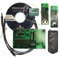
KIT DEVELOPMENT KEELOQ 3
Manufacturer
Microchip Technology
Type
KeeLoq®r
Datasheet
1.DM303007.pdf
(48 pages)
Specifications of DM303007
Frequency
433.92MHz
Processor To Be Evaluated
PIC16F886
Data Bus Width
8 bit
Interface Type
USB
Silicon Manufacturer
Microchip
Core Architecture
PIC
Core Sub-architecture
PIC16
Silicon Core Number
PIC16F
Silicon Family Name
PIC16F8xxx
Kit Contents
MCU, 2x Programmable Transmitter Boards, Receiver Board,
Rohs Compliant
Yes
Lead Free Status / RoHS Status
Lead free / RoHS Compliant
Lead Free Status / RoHS Status
Lead free / RoHS Compliant, Lead free / RoHS Compliant


5.6
5.7
5.8
5.9
5.10
© 2009 Microchip Technology Inc.
RECEIVER BOARD SELECTOR PIN
PICtail™ CONNECTOR
LCD DISPLAY
MAIN PROCESSOR
POWER SUPPLY AND PROTOTYPING AREA
The controller board contains an ASK radio receiver module. The pinout corresponds
to the standard PICtail™ connector. Thus, it may be easily replaced with similar models
accommodating other frequencies, modulation methods (ASK vs. FSK) as well as
adapting transponder boards for two-way communication.
On the controller board there is a jumper (J5) that allows for receiver card selection.
The K
FSK transceiver card is available. The jumper configuration is:
• ASK receiver board: pins 1 and 2 connected, jumper to the left side
• FSK board: pins 2 and 3 connected, jumper to the right side.
• J5 also allows the radio receiver output to be disconnected from the main
The board features two connectors. One 14 pin is dedicated for the receiver modules.
While the connector has 14 pins, not all the pins are used. The ASK receiver board only
uses the following pins:
• Pin 11 – RF data out
• Pin 13 – V
• Pin 14 – GND
The board also features a 28-pin connector that provides an easy access to all of the
PIC16F886 pins.
A 2-line by 16 characters LCD display is present on the board. It is used to display.
When the controller receives a K
data will be shown on the display. The LCD contrast can be adjusted by the contrast
pot located on the bottom side of the controller board, near push button PB1.
The main processor contains a SOIC PIC16F886 operating at 8 MHz. The
microcontroller provides connections for the LCD display, programming, push buttons,
LEDs and RF board control. Please refer to the schematic in Appendix A. “KeeLoq®
3 Development Kit Schematics” for further information.
The power supply circuit is designed to regulate a maximum current of 100 mA at 5V
from an external 9V power supply.
The prototyping area includes convenient V
custom circuitry. The user must ensure that the Prototype area custom circuit current
draw added to the controller board consumption does not exceed the 100 mA total limit.
processor. This permits monitoring the receiver output on an oscilloscope or
injecting an encoder’s digital output directly into the decoder.
EE
L
OQ
DD
3 Development Kit is supplied with the ASK receiver board. Optionally, an
K
5V
EE
L
OQ
®
EE
Development Kit Controller
L
OQ
transmission, the serial code and the decrypted
DD
. and GND through hole strips to power
DS41378A-page 31
Related parts for DM303007
Image
Part Number
Description
Manufacturer
Datasheet
Request
R

Part Number:
Description:
Manufacturer:
Microchip Technology Inc.
Datasheet:
Part Number:
Description:
Manufacturer:
Microchip Technology Inc.
Datasheet:
Part Number:
Description:
Manufacturer:
Microchip Technology Inc.
Datasheet:
Part Number:
Description:
Manufacturer:
Microchip Technology Inc.
Datasheet:
Part Number:
Description:
Manufacturer:
Microchip Technology Inc.
Datasheet:
Part Number:
Description:
Manufacturer:
Microchip Technology Inc.
Datasheet:
Part Number:
Description:
Manufacturer:
Microchip Technology Inc.
Datasheet:
Part Number:
Description:
Manufacturer:
Microchip Technology Inc.
Datasheet: