EM260-BBRD-128K-USART-R Ember, EM260-BBRD-128K-USART-R Datasheet - Page 26
EM260-BBRD-128K-USART-R
Manufacturer Part Number
EM260-BBRD-128K-USART-R
Description
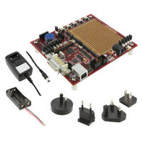
EM260 BREAKOUT BOARD
Manufacturer
Ember
Type
Transceiver, 802.15.4/ZigBeer
Datasheet
1.EM260-RCM-USART-R.pdf
(54 pages)
Specifications of EM260-BBRD-128K-USART-R
Frequency
2.4GHz
For Use With/related Products
EM260
Lead Free Status / RoHS Status
Lead free / RoHS Compliant
Other names
636-1026


5.4
120-0260-000J
Data Format
Table 14 lists the timing parameters of the SPI Protocol. These parameters are illustrated in Figure 7.
The data format, also referred to as a command, is the same for both the Command section and the Response
section. The data format of the SPI Protocol is straightforward, as illustrated in Figure 8.
The total length of a command must not exceed 136 bytes.
All commands must begin with the SPI Byte. Some commands are only two bytes—that is, they contain the SPI
Byte and Frame Terminator only.
The Length Byte is only included if there is information in the Payload Frame and the Length Byte defines the
length of just the Payload Frame. Therefore, if a command includes a Payload Frame, the Length Byte can
have a value from 2 through 133 and the overall command size will be 5 through 136 bytes. The SPI Byte can
be a specific value indicating if there is a Payload Frame or not, and if there is a Payload Frame, then the
Length Byte can be expected.
The Error Byte is used by the error responses to provide additional information about the error and appears in
place of the length byte. This additional information is described in the following sections.
The Payload Frame contains the data needed for operating EmberZNet. The EZSP Frame and its format are
explained in the EZSP Reference Guide (120-3009-000). The Payload Frame may also contain the data needed
for operating the bootloader, which is called a Bootloader Frame. Refer to the EmberZNet Application
Developer’s Guide (120-4028-000) for more information on the bootloader.
The Frame Terminator is a special control byte used to mark the end of a command. The Frame Terminator
byte is defined as
byte. The purpose of the Frame Terminator is to provide a known byte the SPI Protocol can use to detect a
Parameter
t1 (a)
t1 (b)
t2
t3
t4 (a)
t4 (b)
t5
t6
t7
t8
t9
t10
SPI Byte
Length or
Error
0xA7
Description
Wake handshake, while 260 is awake
Wake handshake, while 260 is asleep
Wake handshake finish
Reset pulse width
Startup time, entering application
Startup time, entering bootloader
nHOST_INT deasserting after Command
Clock rate
Wait section
nHOST_INT deasserting after Response
nHOST_INT asserting after transaction
Inter-command spacing
and is appended to all Commands and Responses immediately after the final data
Table 14. SPI Protocol Timing Parameters
Figure 8. SPI Protocol Data Format
Page 26
Payload Frame (Variable Length)
Min.
200
1.1
13
25
20
25
1
8
Typ.
133
250
755
130
7.3
1.2
2.5
35
70
200000
Max.
1500
150
800
800
7.5
10
25
75
EM260
Terminator
Frame
Unit
ms
ms
ms
μs
μs
μs
μs
ns
μs
μs
μs
s
Related parts for EM260-BBRD-128K-USART-R
Image
Part Number
Description
Manufacturer
Datasheet
Request
R

Part Number:
Description:
KIT DEV EMBER ZIGBEE W/PCWH
Manufacturer:
Custom Computer Services Inc (CCS)

Part Number:
Description:
PROGRAMMER USB FLASH EM250/260
Manufacturer:
Ember
Datasheet:

Part Number:
Description:
IC ZIGBEE SYSTEM-ON-CHIP 40-QFN
Manufacturer:
Ember
Datasheet:

Part Number:
Description:
IC ZIGBEE SYSTEM-ON-CHIP 48-QFN
Manufacturer:
Ember
Datasheet:
Part Number:
Description:
IC RF TXRX ZIGBEE 128KB 48QFN
Manufacturer:
Ember
Datasheet:
Part Number:
Description:
IC RF TXRX ZIGBEE 192KB 48QFN
Manufacturer:
Ember
Datasheet:

Part Number:
Description:
INSIGHT ADAPTER FOR EM2XX
Manufacturer:
Ember
Datasheet:

Part Number:
Description:
IAR EWARM LICENCE FOR EM35X
Manufacturer:
Ember
Datasheet:

Part Number:
Description:
KIT EVAL EM250 RF TEST
Manufacturer:
Ember
Datasheet:

Part Number:
Description:
INSIGHT ADAPTER 3 FOR EM35X
Manufacturer:
Ember
Datasheet:

Part Number:
Description:
EM250 RCM BOARD
Manufacturer:
Ember
Datasheet:

Part Number:
Description:
EM35X BREAKOUT BOARD
Manufacturer:
Ember
Datasheet:

Part Number:
Description:
EM260 RCM BOARD
Manufacturer:
Ember
Datasheet:

Part Number:
Description:
EM250 BREAKOUT BOARD
Manufacturer:
Ember
Datasheet:

Part Number:
Description:
KIT JUMP START FOR EM250
Manufacturer:
Ember
Datasheet: