DVK-BTM521 Laird Technologies, DVK-BTM521 Datasheet - Page 31
DVK-BTM521
Manufacturer Part Number
DVK-BTM521
Description
BT MM DEV KIT
Manufacturer
Laird Technologies
Type
Transceiver, Bluetoothr
Specifications of DVK-BTM521
Frequency
2.4GHz
Interface Type
RS-232
Processor Series
BTM521
Silicon Manufacturer
Laird Technologies
Kit Application Type
Communication & Networking
Application Sub Type
Bluetooth
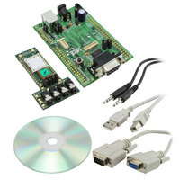
Kit Contents
Development Board & Software Tools
Features
Supports CSR
Rohs Compliant
Yes
For Use With/related Products
BTM521
Lead Free Status / RoHS Status
Lead free / RoHS Compliant
Lead Free Status / RoHS Status
Lead free / RoHS Compliant, Lead free / RoHS Compliant
Other names
DVK-BTM521
Available stocks
Company
Part Number
Manufacturer
Quantity
Price
Company:

Part Number:
DVK-BTM521-01
Manufacturer:
LAIRD
Quantity:
7


BTM520/521
Bluetooth
AT COMMAND SET
REFERENCE
31 www.lairdtech.com
®
Multimedia Plus Module
Bluetooth Profiles
This section covers S-Registers and AT-Commands that are related to supported Bluetooth Profiles on BTM.
Phase
Preparation
Preparation
7. AT+BTR
8
1. Profile Activation
2. SPP (Serial Port Profile)
The second method is initiated by resetting the device and then ensuring that the text string
“AT+BT&BISM&<cr>” is sent (where <cr> is the carriage return character). There is special code which
looks out for this magic command and terminates the autoconnect cycle if it sees it and confirms to
the host of that fact by sending an “OK” response.
Response: <cr,lf>OK<cr,lf>
This command is used to delete the peer address previously stored using AT+BTR<bd_addr>.
Response: <cr,lf>OK<cr,lf>
AT+BTR? {Read Outgoing Peer Address}
This command is used to display the peer address stored in non-volatile memory, used to put the device
in pure cable replacement mode.
Response: <cr,lf>12346789012
<cr,lf>OK<cr,lf>
If the location is empty the response is as follows.
Response: <cr,lf>00000000000
<cr,lf>OK<cr,lf>
In order to activate available profiles and advertise them to potential client devices, S-Register 102 is
used. Per default, only SPP is activated (value=1). Other supported profiles can be activated by setting
the appropriate Flag in S-Register 102. Once S-Register 102 has been written, the changed value needs
to be saved to non-volatile memory (“AT&W”) and subsequently a reset (“ATZ”) or power cycle is
required. Please note that “AT&W” saves the content of all S Registers to non-volatile memory.
The serial port profile (SPP) is used for serial data transmission with a remote device in both directions.
It behaves like a wireless replacement for a serial cable.
SSP belongs to the group of serial stream oriented profiles (SSO) so please refer to page 26 too.
In order to use SPP, the profile must be enabled in S102 (value=1). If it was not enabled earlier, set the
S register accordingly and issue AT&W followed by ATZ.
2.1 SPP Example
This section gives an example on how an SPP connection between two Laird Technologies BTM
devices can be established. It is assumed that two devices A and B are connected to a terminal
program e.g. Ezurio Terminal on a PC. The example sequence of AT commands is listed in Table 3.9.
Figure 3.2 through to Figure 3.5 are presenting appropriate screenshots with Ezurio Terminal.
Dev.
A
B
{Delete Outgoing Peer Address}
AT Command
AT&F*
ATS102=1
AT&W
ATZ
AT&F*
ATS102=1
ATS0=1
AT&W
ATZ
AT+BTP
ATI4
Comment
Restore factory default settings
Enable Serial Port Profile (SPP)
Store settings
Reset
Restore factory default settings
Enable Serial Port Profile (SPP)
Automatic response after one “RING”
Store settings
Reset
Make device temporary connectable and discoverable
Query Bluetooth device address of local device <BdAddr_DevB>
Laird Technologies
Related parts for DVK-BTM521
Image
Part Number
Description
Manufacturer
Datasheet
Request
R

Part Number:
Description:
BLUETOOTH EVAL BOARD BTM511
Manufacturer:
Laird Technologies
Datasheet:

Part Number:
Description:
Bluetooth / 802.15.1 Modules & Development Tools BLUETTH AT Data MODLE, No ANT DEVKIT
Manufacturer:
Laird Technologies
Part Number:
Description:
Bluetooth / 802.15.1 Modules & Development Tools BLUETTH Multimed MODLE, No ANT DEVKIT
Manufacturer:
Laird Technologies
Datasheet:

Part Number:
Description:
BLUETOOTH MODULE DEVELOPMENT KIT
Manufacturer:
Laird Technologies
Part Number:
Description:
Bluetooth 2.0 AT Data Module, Internal Antenna Development Kit
Manufacturer:
Laird Technologies
Part Number:
Description:
Bluetooth / 802.15.1 Modules & Development Tools BLUETTH HCI Data MDLE INTRNLANT DVKIT
Manufacturer:
Laird Technologies
Datasheet:
Part Number:
Description:
Bluetooth / 802.15.1 Modules & Development Tools BLUETTHMultimedMODLE Plus No Ant DEVKIT
Manufacturer:
Laird Technologies
Part Number:
Description:
Bluetooth / 802.15.1 Modules & Development Tools BLUETTH HCI Data MDLE No ANT DVKIT
Manufacturer:
Laird Technologies
Datasheet:

Part Number:
Description:
KIT FOR PRM113
Manufacturer:
Laird Technologies
Datasheet:

Part Number:
Description:
DEV KIT PRM122
Manufacturer:
Laird Technologies
Datasheet:
Part Number:
Description:
DEV KIT PRM123
Manufacturer:
Laird Technologies
Datasheet:

Part Number:
Description:
KIT FOR PRM112
Manufacturer:
Laird Technologies
Datasheet:
Part Number:
Description:
DEV KIT PRM121
Manufacturer:
Laird Technologies
Datasheet:

Part Number:
Description:
KIT DEVELOPMENT FOR LT2510 U.FL
Manufacturer:
Laird Technologies
Datasheet:

Part Number:
Description:
Bluetooth / 802.15.1 Modules Class2 v2.1+EDR Kit AT Data, Int Ant,SSP
Manufacturer:
Laird Technologies Wireless M2M
Datasheet: