DR-TRC105-390-DK RFM, DR-TRC105-390-DK Datasheet - Page 7
DR-TRC105-390-DK
Manufacturer Part Number
DR-TRC105-390-DK
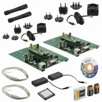
Description
DEV KIT TRC105
Manufacturer
RFM
Type
Transceiverr
Specifications of DR-TRC105-390-DK
Frequency
390MHz
Maximum Frequency
398 MHz
Antenna
SMA
Supply Voltage (max)
12 V
Supply Voltage (min)
4.5 V
Minimum Frequency
382 MHz
Product
RF Modules
For Use With/related Products
TRC105
Lead Free Status / RoHS Status
Lead free / RoHS Compliant
Other names
583-1155


Kit Testing using the RFIC Design Assistant
www.RFM.com
©2009-2010 by RF Monolithics, Inc.
1. Install the RFIC Design Assistant utility program from the kit CD. If you are using
2. If installed, remove the 9 volt batteries from the board sets. Install the antennas
3. Connect one of the board sets to the PC. Turn on the board set by sliding the
4. Start the RFIC Design Assistant utility program as shown in Figure 7. Select the
5. Select the TRC105 from the TRC drop-down menu as shown in Figure 8. This
6. Select the Main Menu tab and click on the Read Configuration button. A hex
the USB interface, install the virtual COM port drivers. Refer to the USB Virtual
COM Ports section of the RFIC Design Assistant User’s Guide on the CD for
driver installation details.
as needed and then connect a 4.5 volt wall-plug power supply to each board set.
Power switch on the interface board to the ON position. All LED’s on the radio
board will flash and the MODE LED will be green.
COM port or virtual COM port assigned to the board set from the drop-down
menu at the top of the utility program screen. The COM port can be determined
from Windows® as follows: Start > Settings > Control Panel > System >
Hardware > Device Manager > Ports (COM & LPT).
will launch the TRC105 multi-tab dialog window as shown in Figure 9
dump of the current TRC105 configuration parameters should appear in the text
box above the button as shown in Figure 9. This confirms the development board
set is communicating with the utility program. Test the other development kit
board set in the same manner. The development kit is now ready to use.
Figure 6 - Initial Testing Using Range Test Function
Technical support +1.800.704.6079
E-mail:
info@rfm.com
DR-TRC105-DK - 04/05/10
Page 7 of 27
Related parts for DR-TRC105-390-DK
Image
Part Number
Description
Manufacturer
Datasheet
Request
R

Part Number:
Description:
DEV KIT TRC105
Manufacturer:
RFM
Datasheet:

Part Number:
Description:
DEV KIT TRC105
Manufacturer:
RFM
Datasheet:

Part Number:
Description:
DEV KIT TRC105
Manufacturer:
RFM
Datasheet:

Part Number:
Description:
DEV KIT TRC105
Manufacturer:
RFM
Datasheet:

Part Number:
Description:
DEV KIT TRC105
Manufacturer:
RFM
Datasheet:

Part Number:
Description:
DEV KIT TRC105
Manufacturer:
RFM
Datasheet:

Part Number:
Description:
DEV KIT TRC105
Manufacturer:
RFM
Datasheet:

Part Number:
Description:
RF Modules & Development Tools TRC105 Evaluation Board 447-451 MHz
Manufacturer:
RFM
Datasheet:
Part Number:
Description:
RF Modules & Development Tools TRC105 Evaluation Board 365-381 MHz
Manufacturer:
RFM
Datasheet:
Part Number:
Description:
RF Modules & Development Tools TRC105 Evaluation Board 303-307 MHz
Manufacturer:
RFM
Datasheet:

Part Number:
Description:
WiFi / 802.11 Modules 2.4 and 5.8GHz + BT
Manufacturer:
RFM
Datasheet:

Part Number:
Description:
10-Terminal Ceramic Surface-Mount Case 7 x 5 mm Nominal Footprint
Manufacturer:
RFM [RF Monolithics, Inc]
Datasheet:
Part Number:
Description:
QUAD-BAND GSM850/GSM/DCS/PCS POWER AMP MODULE
Manufacturer:
RFM [RF Monolithics, Inc]
Datasheet:
Part Number:
Description:
402 to 405 MHz Medical Band Front-end Filter
Manufacturer:
RFM [RF Monolithics, Inc]
Datasheet: