1000-TCB1C470 Silicon Laboratories Inc, 1000-TCB1C470 Datasheet - Page 6
1000-TCB1C470
Manufacturer Part Number
1000-TCB1C470
Description
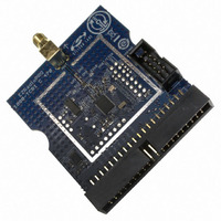
BOARD EVALUATION FOR SI1000
Manufacturer
Silicon Laboratories Inc
Type
Transceiver, ISMr
Specifications of 1000-TCB1C470
Mfg Application Notes
SI1000 Code Examples AppNote
Frequency
470MHz
Supply Voltage (min)
0.9 V
Product
RF Modules
Maximum Frequency
915 MHz
Output Power
20 dBm
Antenna
SMA
Supply Voltage (max)
3.6 V
For Use With/related Products
Si100x
Lead Free Status / RoHS Status
Lead free / RoHS Compliant
Lead Free Status / RoHS Status
Lead free / RoHS Compliant, Lead free / RoHS Compliant
Other names
336-1893


Si10xx-DK
Since supply current is typically dependent on supply voltage, the discharge profile editor provides two columns for
supply current. The V2 and V1 voltages at the top of the two columns specify the voltages at which the current
measurements were taken. The Battery Life Estimator creates a linear approximation based on the input data and
is able to feed the simulation engine with an approximate supply current demand for every input voltage.
The minimum system operating voltage input field allows the system operating time to stop increasing when the
simulated battery voltage drops below a certain threshold. This is primarily to allow operating time estimates for
systems that cannot operate down to 1.8 V, which is the voltage of two fully drained single-cell batteries placed in
series.
The wakeup frequency box calculates the period of a single iteration through the four power modes and displays
the system wake up frequency. This is typically the "sample rate" in low power analog sensors.
Once the battery type and discharge profile is specified, the user can click the "Simulate" button to start a new
simulation. The simulation engine calculates the estimated battery life when using one single-cell battery, two
single-cell batteries in series, and two single-cell batteries in parallel. Figure 5 shows the simulation output window.
Figure 5. Battery Life Estimator Utility Simulation Results Form
The primary outputs of the Battery Life Estimator are an estimated system operating time and a simulated graph of
battery voltage vs. time. Additional outputs include estimated battery capacity, average current, self-discharge
current, and the ability to export graph data to a comma delimited text file for plotting in an external graphing
application.
6
Rev. 0.1
Related parts for 1000-TCB1C470
Image
Part Number
Description
Manufacturer
Datasheet
Request
R


Part Number:
Description:
BOARD EVALUATION FOR SI1000
Manufacturer:
Silicon Laboratories Inc
Datasheet:

Part Number:
Description:
Industrial Pressure Sensors Force Sensor 20mV/V 1000 lbf Compression
Manufacturer:
Measurement Specialties Inc.
Datasheet:

Part Number:
Description:
MODULE NETWORK 915MHZ
Manufacturer:
Helicomm Inc
Datasheet:

Part Number:
Description:
Transformers Auto 230V/115V
Manufacturer:
Stancor
Datasheet:
Part Number:
Description:
Transformers Isolation 230V/115V
Manufacturer:
Stancor
Datasheet:
Part Number:
Description:
Transformers Isolation 115V/115V
Manufacturer:
Stancor
Datasheet:

Part Number:
Description:
1000 FT SPOOL, PTFE COVERED WIRE
Manufacturer:
NEWPORT ELECTRONICS

Part Number:
Description:
1000' STRANDED CAT5E CABLE (YELLOW),ROHS
Manufacturer:
BELKIN

Part Number:
Description:
SMD/C�/SINGLE-ENDED OUTPUT SILICON OSCILLATOR
Manufacturer:
Silicon Laboratories Inc
Part Number:
Description:
Manufacturer:
Silicon Laboratories Inc
Datasheet:
Part Number:
Description:
N/A N/A/SI4010 AES KEYFOB DEMO WITH LCD RX
Manufacturer:
Silicon Laboratories Inc
Datasheet:
Part Number:
Description:
N/A N/A/SI4010 SIMPLIFIED KEY FOB DEMO WITH LED RX
Manufacturer:
Silicon Laboratories Inc
Datasheet: