MDEV-LICAL-MS Linx Technologies Inc, MDEV-LICAL-MS Datasheet - Page 4
MDEV-LICAL-MS
Manufacturer Part Number
MDEV-LICAL-MS
Description
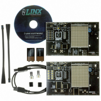
DEV SYSTEM MS SERIES 418MHZ
Manufacturer
Linx Technologies Inc
Series
MSr
Type
Encoder, Decoderr
Datasheet
1.MDEV-LICAL-MS.pdf
(7 pages)
Specifications of MDEV-LICAL-MS
Supply Voltage (min)
7 V
Product
RF Development Tools
Supply Voltage (max)
16 V
Lead Free Status / RoHS Status
Contains lead / RoHS non-compliant
For Use With/related Products
MS Series Encoder and Decoder
Lead Free Status / Rohs Status
Lead free / RoHS Compliant
Other names
MDEV-LIC-MS
MDEV-LIC-MS
MDEV-LIC-MS


THE ENCODER BOARD (CONT.)
Page 6
Figure 4: The Encoder Board RF Area
The Encoder Board RF Area
Beneath the LEDs is a button that is connected to the CREATE line. This button
is used to create the Code Word and set the Control Permissions as described
in the MS Series Encoder Data Guide.
There are three function switches to
the left of the CREATE button.
BSEL0 and BSEL1 are used to set
the baud rate of the encoder as
described in the adjacent table.
*Important* The decoder board must
be set to the same baud rate in order
for the signal to be received correctly.
The maximum baud rate for the LR Series is 10,000bps, so only 2,400 and
9,600bps can be used on boards populated with these modules. The ES Series
can use all four baud rates.
The PDN switch will connect the TX_CNTL line of the encoder to the PDN line
of the transmitter so that the TX Control Mode of the encoder can be tested. This
mode is described in the MS Series Encoder Data Guide.
If a BSEL switch is up, then the line is high (1, V
(0, GND). If the PDN switch is up, then the encoder’s TX_CNTL line is connected
to the transmitter’s PDN line; if down, it is not connected and the LR Series
transmitter will not be activated unless the PDN line is pulled high externally. The
ES Series transmitter has an internal pull-up, so will be active unless pulled low.
The figure below shows the RF area of the development board.
This board can be populated with either the LR Series transmitter (as shown) or
the ES Series transmitter. The LR Series transmitter will be placed on the right
side and the ANT1 connector will be populated. The ES Series transmitter will be
placed on the left and the ANT2 connector will be populated. R27 is connected
to the LADJ line of the LR transmitter to reduce the output power to
approximately 0dBm. The LR Series transmitter is capable of producing more
output power than may be legally acceptable, so by reducing the output power
the range experienced with the evaluation kit will more closely resemble the rage
that can be achieved with a final certified product.
Table 1: Baud Rate Selection Table
BSEL1
0
0
1
1
CC
); if down, then the line is low
BSEL0
0
1
0
1
Baud Rate
19,200
28,800
2,400
9,600
THE DECODER BOARD
Figure 5: The Decoder Area
The Decoder Area
The decoder board has three main sections of interest: the decoder area, the
receiver area, and the USB area.
The figure below shows the decoder area of the development board.
The decoder is placed in the center beneath the Linx logo. To the left are LEDs
that are connected to the decoder data lines. These will light up when the
decoder receives a signal from the encoder to take the data line high. LED D0
corresponds to data line D0 and so forth.
Beneath the decoder are two LEDs. D12 is connected to the MODE_IND line
and will light up as described in the MS Series Decoder Data Guide. D8 is
connected to the RX_CNTL line and will provide visual feedback by lighting up
when the decoder activates the receiver when in RX Control Mode.
Beneath the LEDs is a button that is connected to the LEARN line. This button
is used to learn the Code Word from the encoder as described in the MS Series
Decoder Data Guide.
There are four function switches to the left of the CREATE button. BSEL0 and
BSEL1 are used to set the baud rate of the decoder as described in Table 1.
*Important* The encoder board must be set to the same baud rate in order for
the signal to be received correctly. The maximum baud rate for the LR Series is
10,000bps, so only 2,400 and 9,600bps can be used on boards populated with
these modules. The ES Series receiver can use all four baud rates. If the switch
is up, then the line is high, if it is down, then the line is low.
The PDN switch will connect the RX_CNTL line of the encoder to the PDN line
of the receiver so that the RX Control Mode of the decoder can be tested. This
mode is described in the MS Series Decoder Data Guide.
The LATCH switch will place the decoder into Latch Mode when on, so that the
data lines will go high when a valid signal is received and stay high until a second
valid signal is received. If the switch is off, the data lines are momentary.
Page 7
Related parts for MDEV-LICAL-MS
Image
Part Number
Description
Manufacturer
Datasheet
Request
R

Part Number:
Description:
DEV SYSTEM HS SERIES 418MHZ
Manufacturer:
Linx Technologies Inc
Datasheet:

Part Number:
Description:
KIT MASTER 900MHZ HP-3 SIP RS232
Manufacturer:
Linx Technologies Inc
Datasheet:

Part Number:
Description:
KIT MASTER DEV 916MHZ ES RS232
Manufacturer:
Linx Technologies Inc
Datasheet:

Part Number:
Description:
KIT DEV MASTER USB QS SERIES
Manufacturer:
Linx Technologies Inc
Datasheet:

Part Number:
Description:
KIT MASTER DEV MS KEYFOB 418MHZ
Manufacturer:
Linx Technologies Inc
Datasheet:

Part Number:
Description:
KIT DEV MS HANDHELD TX 418MHZ
Manufacturer:
Linx Technologies Inc
Datasheet:
Part Number:
Description:
KIT MASTER DEV MS KEYFOB 433MHZ
Manufacturer:
Linx Technologies Inc
Datasheet:

Part Number:
Description:
KIT DEV TX 433MHZ HS COMPACT
Manufacturer:
Linx Technologies Inc
Datasheet:

Part Number:
Description:
KIT DEV TX 418MHZ HS COMPACT
Manufacturer:
Linx Technologies Inc
Datasheet:

Part Number:
Description:
KIT DEV TX 315MHZ MS SERIES
Manufacturer:
Linx Technologies Inc
Datasheet:

Part Number:
Description:
MODULE USB LOW SPEED
Manufacturer:
Linx Technologies Inc
Datasheet:

Part Number:
Description:
IC TRANSCODER MT BI-DIR 20-SSOP
Manufacturer:
Linx Technologies Inc
Datasheet:

Part Number:
Description:
IC ENCODER LOW SECURITY 8DIP
Manufacturer:
Linx Technologies Inc
Datasheet:

Part Number:
Description:
IC DECODER MS SERIES 20-SSOP
Manufacturer:
Linx Technologies Inc
Datasheet:
Part Number:
Description:
IC ENCODER MS SERIES 20-SSOP
Manufacturer:
Linx Technologies Inc
Datasheet: