NLB-400-PCK RFMD, NLB-400-PCK Datasheet
NLB-400-PCK
Specifications of NLB-400-PCK
Available stocks


Related parts for NLB-400-PCK


NLB-400-PCK Summary of contents
Page 1
... This 50Ω gain block is based on a reliable HBT pro- prietary MMIC design, providing unsurpassed performance for small-sig- nal applications. Designed with an external bias resistor, the NLB-400 provides flexibility and stability. The NLB-400 is packaged in a low-cost, surface-mount plastic package, providing ease of assembly for high-vol- ume tape-and-reel requirements. ...
Page 2
... NLB-400 Absolute Maximum Ratings Parameter RF Input Power 3 Power Dissipation Device Current Channel Temperature Operating Temperature Storage Temperature Exceeding any one or a combination of these limits may cause permanent damage. Parameter Overall Small Signal Power Gain, S21 Gain Flatness, GF Input VSWR Output VSWR ...
Page 3
... N 4.73 4.88 E NOTE: All dimensions are in millimeters, and the dimensions in inches are for reference only Gauge Plane G 0 NLB-400 Interface Schematic RF OUT RF IN INCHES Min. Nom. Max. 0.021 REF. 2.69 0.094 0.100 0.106 2.49 0.086 0.092 0.098 2.41 0.075 0.085 0.095 1 ...
Page 4
... NLB-400 Application notes related to biasing circuit, device footprint, and thermal considerations are available on request. 3 Recommended Bias Resistor Values Supply Voltage Bias Resistor, R (Ω 7628 Thorndike Road, Greensboro, NC 27409-9421 · For sales or technical support, contact RFMD at (+1) 336-678-5570 or sales-support@rfmd.com. 3-26 Typical Bias Configuration ...
Page 5
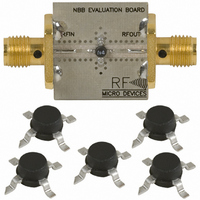
... Extended Frequency InGaP Amplifier Designer’s Tool Kit This tool kit was created to assist in the design-in of the RFMD NBB- and NLB-series InGap HBT gain block amplifiers. Each tool kit contains the following. • 5 each NBB-300, NBB-310 and NBB-400 Ceramic Micro-X Amplifiers • ...
Page 6
... NLB-400 3 All dimensions in mm 0.30 ± 0.05 R0.3 MAX. SECTION A-A NOTES sprocket hole pitch cumulative tolerance ±0.2. 2. Camber not to exceed 100 mm. 3. Material: PS+ and Bo measured on a plane 0.3 mm above the bottom of the pocket measured from a plane on the inside bottom of the pocket to the surface of the carrier. ...
Page 7
... Noise Figure versus Frequency at +25°C 6.0 5.0 4.0 3.0 2.0 25°C 1.0 40°C 85°C 0.0 10.0 12.0 0.0 2.0 NLB-400 S21, +25°C S21, -40°C S21, +85°C 3.0 4.0 5.0 6.0 7.0 8.0 Frequency (GHz) S22, +25°C S22, -40°C S22, +85°C 3.0 4 ...
Page 8
... NLB-400 Note: The s-parameter gain results shown include device performance as well as evaluation board and connector loss varia- tions. The insertion losses of the evaluation board and connectors are as follows: 1GHz to 4GHz=-0.06dB 5GHz to 9GHz=-0.22dB 3 10GHz to 14GHz=-0.50dB 15GHz to 20GHz=-1.08dB RoHS Compliant: ...