DR7003-DK RFM, DR7003-DK Datasheet - Page 6
DR7003-DK
Manufacturer Part Number
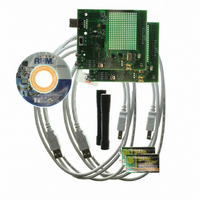
DR7003-DK
Description
3G DEVELOPMENT KIT 303.825 MHZ
Manufacturer
RFM
Type
Transceiverr
Datasheets
1.DR7000-DK.pdf
(8 pages)
2.DR7000-DK.pdf
(3 pages)
3.DR7000-DK.pdf
(16 pages)
4.DR7003-DK.pdf
(7 pages)
Specifications of DR7003-DK
Frequency
303.825MHz
For Use With/related Products
DR7003
Lead Free Status / RoHS Status
Lead free / RoHS Compliant
Other names
583-1047


RF Monolithics, Inc.
Rev1
Should an error occur in the checksum, the Error LED (RED) will flash momentarily indicating a
failed packet.
2.7 Current Monitor (J8)
2.8 TX Range Test Configuration Jumper (J5)
The current monitor allows for the developer to monitor the current that ONLY the TRXXXX device is
using. By removing the jumper installed at J8 (see Figure 7) and connecting an ammeter across the two
pins, the current usage of the TRXXXX device may be monitored. Connecting the ammeter must be
performed BEFORE powering the board.
By placing the shorting jumper on J5 (see Figure 8) the board is configured for a Range Test transmitter at
power-up. Before moving the switch SW1 to “ON” the jumper must be installed. After installation, move
the switch to the “ON” position. The four LED’s will sequence and the “heartbeat” LED will flash as well as
the TX packet and serial traffic indicators (see section 2.4). Each time a packet is sent the TX indicator
will flash. The TX indicator LED will flash rapidly indicating Range Test packet transmission. Refer to
Figure 9.
Figure 8. Range Test Jumper
(800) 704-6079 toll-free in U.S. and Canada
Figure 7. Current Monitor Jumper J8
Figure 6. USB Power on LED
Figure 9. LED Indicators for Range Test
www.rfm.com
Email: support@rfm.com
LEDs flash
rapidly!
6
Related parts for DR7003-DK
Image
Part Number
Description
Manufacturer
Datasheet
Request
R

Part Number:
Description:
RF Modules & Development Tools 3G Transceiver Eval Module 303.825 MHz
Manufacturer:
RFM
Datasheet:
Part Number:
Description:
RF Transceiver 3G Transceiver Module 303.825 MHz
Manufacturer:
RFM
Datasheet:

Part Number:
Description:
ASH RX 115.2 KBPS 433.92 MHZ
Manufacturer:
RFM
Datasheet:

Part Number:
Description:
RFIC TRANCEIVER MULTI-CHANNEL FS
Manufacturer:
RFM
Datasheet:

Part Number:
Description:
ASH TX 115.2 KBPS 433.92 MHZ
Manufacturer:
RFM
Datasheet:
Part Number:
Description:
Filters 1602MHz BW=61MHz
Manufacturer:
RFM
Datasheet:

Part Number:
Description:
RESONATOR, SM3030-6
Manufacturer:
RFM
Datasheet:

Part Number:
Description:
RESONATOR, SM3030-6
Manufacturer:
RFM
Datasheet:

Part Number:
Description:
RESONATOR, SM3030-6
Manufacturer:
RFM
Datasheet:

Part Number:
Description:
RESONATOR, SM5035-4
Manufacturer:
RFM
Datasheet:

Part Number:
Description:
10-Terminal Ceramic Surface-Mount Case 7 x 5 mm Nominal Footprint
Manufacturer:
RFM [RF Monolithics, Inc]
Datasheet:
Part Number:
Description:
QUAD-BAND GSM850/GSM/DCS/PCS POWER AMP MODULE
Manufacturer:
RFM [RF Monolithics, Inc]
Datasheet:
Part Number:
Description:
402 to 405 MHz Medical Band Front-end Filter
Manufacturer:
RFM [RF Monolithics, Inc]
Datasheet:
Part Number:
Description:
674.03 MHz SAW Resonator
Manufacturer:
RFM [RF Monolithics, Inc]
Datasheet: