DR8000-DK RFM, DR8000-DK Datasheet
DR8000-DK
Specifications of DR8000-DK


Related parts for DR8000-DK


DR8000-DK Summary of contents
Page 1
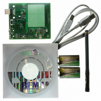
... DR7000-DK (433.92 MHz) • DR7001-DK (315.00 MHz) • DR7003-DK (303.825 MHz) • DR8000-DK (916.5 MHz) • DR8001-DK (868.35 MHz) • DR8100-DK (916.5 MHz w/DSSS) The 3G Development kits allows for complete evaluation and application development of RFM’s SRR (Short Range Radio) line of RFIC’s. A communication link or Range Test can be executed with the Data Terminal to evaluate system performance ...
Page 2
... Current Monitor (J8) ............................................................................................ 6 2.8 TX Range Configuration Jumper (J5)................................................................. 6 2.9 Test Points............................................................................................................ 7 2.10 Custom Development Area ............................................................................... 7 2.11 Communication Link Protocol .......................................................................... 7 2.12 Communication Packet ..................................................................................... 8 2.13 3G VWO Configuration Software ...................................................................... 8 Rev1 RF Monolithics, Inc. (800) 704-6079 toll-free in U.S. and Canada TABLE OF CONTENTS www.rfm.com 5 2 Email: support@rfm.com ...
Page 3
... Unless you have access to this type of equipment, the use of an antenna consultant is recommended. Rev1 RF Monolithics, Inc. (800) 704-6079 toll-free in U.S. and Canada Figure 1. 3G VWO Development Board www.rfm.com 3 Email: support@rfm.com ...
Page 4
... For development using the on-board Silicon Labs C8051F330 microcontroller, a header is available for programming and debug capability using the Silicon Labs USB Debug Adapter module (sold separately). Full development is possible by purchasing the C8051F330DK Development Kit. All firmware code for the development kit is available from the RFM website. Figure 2. Development/Programming Connection 2.3 Power Supply The development board may be powered from one of three methods: 9V battery, USB port, or external power supply applied to J1 ...
Page 5
... When the USB port is connected, a Green LED will light indicating that a connection is established and ready for power-up. Refer to Figure 6. Rev1 RF Monolithics, Inc. (800) 704-6079 toll-free in U.S. and Canada Serial (COM) Traffic Indicator TX Packet Indicator Error Packet Indicator Figure 4. LED Indicators Figure 5. RESET Button www.rfm.com 5 Email: support@rfm.com ...
Page 6
... Should an error occur in the checksum, the Error LED (RED) will flash momentarily indicating a failed packet. Rev1 RF Monolithics, Inc. (800) 704-6079 toll-free in U.S. and Canada Figure 6. USB Power on LED Figure 7. Current Monitor Jumper J8 Figure 9. LED Indicators for Range Test www.rfm.com LEDs flash rapidly! 6 Email: support@rfm.com ...
Page 7
... The protocol software does not require or support hardware flow control, so the host software will have to do some timekeeping to interface the Rev1 RF Monolithics, Inc. (800) 704-6079 toll-free in U.S. and Canada Figure 10. Testpoints Figure 11. Prototyping Area www.rfm.com 7 Email: support@rfm.com ...
Page 8
... The software can Read and Write the internal registers as well as operate in backward- compatible second generation (2G) mode. See the 3G Configuration Software datasheet for detailed operational information. 4441 Sigma Road Dallas, Texas 75244 (800) 704-6079 toll-free in U.S. and Canada Email: info@rfm.com www.rfm.com www.wirelessis.com Rev1 RF Monolithics, Inc. (800) 704-6079 toll-free in U.S. and Canada ...