SG923-0003 Sagrad Inc, SG923-0003 Datasheet - Page 4
SG923-0003
Manufacturer Part Number
SG923-0003
Description
KIT SOFTWARE INTEGRATN SPI/SDIO
Manufacturer
Sagrad Inc
Type
Sagrad Wi-Fi 802.11B/Gr
Datasheet
1.SG923-0003.pdf
(5 pages)
Specifications of SG923-0003
Frequency
2.4GHz
Interface Type
SPI, SDIO
Lead Free Status / RoHS Status
Lead free / RoHS Compliant
Lead Free Status / RoHS Status
Lead free / RoHS Compliant, Lead free / RoHS Compliant
Other names
831-1003


1-321-255-0515
Instructions to connect the SPI interface to the SG909-0034
(SPI 3.3V)
1. Connect a +3.0 to 3.6V (min 200mA) supply to JP1 pin 2. This is required to power the WLAN
2. Connect the SPI Clock to JP1 pin 3
3. Connect the SPI Master out, Slave in (MOSI) to JP1 pin 4
4. Connect the SPI Master in, Slave out (MISO) to JP1 pin 5
5. Connect the SPI Chip Select to JP1 pin 6
6. Connect the power up control to JP1 pin 8. This pin is normally pulled to approximately 2V upon
7. Connect the SPI Interrupt Request (IRQ) to JP1 pin 11
8. Connect the 3.0 to 3.6V supply to JP1 pin 14. This is optional. The WLAN Module has a pull up
9. Pins 7, 9, 10, 13, 15 and 16 are the ground returns for SPI signals and the external power supply.
10. JP1 pin 1 is “no connect”
module Transmit Power Amplifier, voltage regulators, low frequency clock oscillator and TX
controls.
application of the 3V to 3.6V supply, powering the WLAN module on. It is used to power down the
WLAN when grounded.
resistor for enabling SPI operation. This pin selects the SPI/SDIO mode of operation for all
Sagrad modules with the exception of SG901-1030 Wi-Fi module where it becomes the antenna
diversity control.
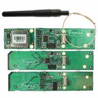
(All tied together in the evaluation board)
evaluation board
WWW.SAGRAD.COM
DOC #: SG923-0010 rev. 3.3
Related parts for SG923-0003
Image
Part Number
Description
Manufacturer
Datasheet
Request
R

Part Number:
Description:
EVAL KIT FOR SG901-1047
Manufacturer:
Sagrad Inc
Datasheet:

Part Number:
Description:
KIT EVALUATION SPI 802.11B/G
Manufacturer:
Sagrad Inc
Datasheet:

Part Number:
Description:
EVAL KIT TXRX 3.3V W/CONNECTOR
Manufacturer:
Sagrad Inc
Datasheet:
Part Number:
Description:
EVAL KIT TXRX 3.3V W/HEADER
Manufacturer:
Sagrad Inc
Datasheet:

Part Number:
Description:
EVAL KIT TXRX 5V W/CONNECTOR
Manufacturer:
Sagrad Inc
Datasheet:
Part Number:
Description:
EVAL KIT TXRX 5V W/HEADER
Manufacturer:
Sagrad Inc
Datasheet:

Part Number:
Description:
EVAL KIT FOR SG901-1071
Manufacturer:
Sagrad Inc
Datasheet:

Part Number:
Description:
RF EVAL FOR SG901-1091
Manufacturer:
Sagrad Inc
Datasheet:

Part Number:
Description:
MODULE WIFI 802.11 B/G/N 3.3V
Manufacturer:
Sagrad Inc
Datasheet:
Part Number:
Description:
MODULE WIFI 802.11 B/G/N 5V
Manufacturer:
Sagrad Inc
Datasheet:

Part Number:
Description:
MODULE WIFI 802.11 B/G/N 3.3V
Manufacturer:
Sagrad Inc
Datasheet:

Part Number:
Description:
MODULE WIFI 802.11 B/G/N 5V
Manufacturer:
Sagrad Inc
Datasheet:
Part Number:
Description:
RF WI-FI MODULE 802.11 B/G/N
Manufacturer:
Sagrad Inc
Datasheet:

Part Number:
Description:
MODULE WIFI 802.11 B/G 3.3V
Manufacturer:
Sagrad Inc
Datasheet:

Part Number:
Description:
MODULE WIFI RADIO 802.11B/G
Manufacturer:
Sagrad Inc
Datasheet: