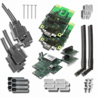
UGWKPA4VEA1-EK Unigen Corp, UGWKPA4VEA1-EK Datasheet - Page 18

UGWKPA4VEA1-EK
Manufacturer Part Number
UGWKPA4VEA1-EK
Description
EVALUATION KIT PAN 400
Manufacturer
Unigen Corp
Series
PANr
Type
Transceiver, UHFr
Specifications of UGWKPA4VEA1-EK
For Use With/related Products
PAN 400
Lead Free Status / RoHS Status
Lead free / RoHS Compliant
Other names
784-1042
Solutions for a Real Time World
ATW1
ATW2
ATW3
ATW4
ATW5
ATR5
ATR6
ATR7
ATR8
ATR9
Write Transmit Content
Read Firmware Version
Write Frequency Offset
Reads Frequency Error
Write Transmit Power
Read Transmit Buffer
Read Radio Module
Read RSSI Value
Select Baseband
Write RF State
Frequency
Copyright 2008 Unigen Corporation. All rights reserved. WWW.UNIGEN.COM
Indicator
- 18 –
ATr11
ATr10
ATr21
ATr20
ATr30
ATr31
ATr40
ATr41
ATr50
ATr51
ATw5
ATw6
ATw7
ATw8
Reads the RSSI value of the radio in
the RX state. Returns the RSSI in a
value response.
Reads the frequency error indicator.
Returns the value of the error
Reads the name of the radio
module. Return a text string of the
name of the module.
Reads the firmware version of the
Vesta motherboard.
Reads the contents in the transmit
buffer and the data to be
transmitted over the radio.
Selects the Baseband Frequency.
Values:
Writes and executes new RF state.
Values:
Writes and executes the new
transmit power state in dBm
Values:
Writes and executes the new
frequency offset.
Value = ± XXXX KHz
XXXX is 4 bytes long
Writes the contents of data to be
transmitted over the air. The
content is a text string. i.e “Hello
World”
a) 0 = 216~218MHz
b) 1 = 433~435MHz
c) 2 = 767~870MHz
d) 3 = 902~928MHz
a) 0 = Sleep Mode
b) 1 = Standby Mode
c) 2 = Receive Mode
d) 3 = Transmit Mode
a) 0 = 0 dBm
b) 1 = 5 dBm
c) 2 = 10 dBm
d) 3 = 15 dBm
PAN Demo Kit
User Guide


