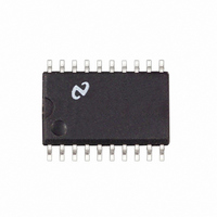
LM1865M National Semiconductor, LM1865M Datasheet - Page 11

LM1865M
Manufacturer Part Number
LM1865M
Description
IC ADVANCED FM IF SYSTEM SO20
Manufacturer
National Semiconductor
Datasheet
1.LM1865N.pdf
(16 pages)
Specifications of LM1865M
Function
FM IF System
Rf Type
FM
Package / Case
20-SOIC (0.300", 7.50mm Width)
Lead Free Status / RoHS Status
Contains lead / RoHS non-compliant
Other names
*LM1865M
Available stocks
Company
Part Number
Manufacturer
Quantity
Price
Company:
Part Number:
LM1865M
Manufacturer:
NSC
Quantity:
5 510
Part Number:
LM1865M
Manufacturer:
NS/国半
Quantity:
20 000
the tuner is not desensitized by the AGC to weak desired
stations below the narrow band threshold
Application Notes
voltage while V
until it reaches the level of the wide band threshold at the
tuner output When this occurs V
keep V
drop as the amount of AGC increases while V
stant by the AGC
When compared to the simple case of a single in-band sig-
nal we see that because of the presence of a strong out-of-
band signal AGC action has occurred earlier For the simple
case AGC started when V
above AGC started when V
achieves an early AGC when there are strong adjacent
channels that might cause IM
signals aren’t present
For the range of signal levels that the tuner was gain-re-
duced and V
the recovered audio as compared to the case where there
was no gain reduction in this interval Note however that
o l
V
D k
WB
D
as V
V
is allowed to increase V
WB
D
there was loss in signal-to-noise in
takes over the job Thus V
D t
3
D t
(Continued)
V
FIGURE 11 Affect of Meter Load on Narrow Band Threshold
and a later AGC when these
WB
UD
V
NB
For the two signal case
is no longer needed to
Thus the LM1865
FIGURE 10 Narrow Band Threshold Circuit
D
D
will increase
is held con-
UD
will
11
10
NARROW BAND AGC THRESHOLD ADJUSTMENT
Both the narrow band and wide band AGC thresholds are
user adjustable This allows the user to optimize the AGC
response to a given tuner Referring to Figure 5 when the
meter output exceeds 1V a comparator closes SW1 A sim-
plified circuit diagram of this comparator is shown in Figure
The 1K resistor in series with pin 8 allows for an upward
adjustment of the narrow band threshold This is accom-
plished by externally loading pin 8 with a resistor Figure 11
illustrates how this adjustment takes place
From Figure 11 it is apparent that loading the meter output
not only moves the narrow band threshold but also de-
creases the meter output for a given input
In general one chooses the narrow band threshold
based on what signal-to-noise compromise is considered
acceptable
TL H 7509 – 13
TL H 7509– 12


