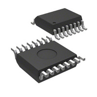
MICRF218AYQS Micrel Inc, MICRF218AYQS Datasheet - Page 18

MICRF218AYQS
Manufacturer Part Number
MICRF218AYQS
Description
IC RCVR QWIKRADIO 3.3V 16-QSOP
Manufacturer
Micrel Inc
Specifications of MICRF218AYQS
Frequency
300MHz ~ 450MHz
Sensitivity
-108dBm
Data Rate - Maximum
10 kbps
Modulation Or Protocol
AM
Applications
ISM, Garage Door Openers, RKE
Current - Receiving
5.5mA
Data Interface
PCB, Surface Mount
Antenna Connector
PCB, Surface Mount
Voltage - Supply
3 V ~ 3.6 V
Operating Temperature
-40°C ~ 85°C
Package / Case
16-QSOP
Receiving Current
5.5mA
Data Rate
10Kbps
Modulation Type
ASK, OOK
Frequency Range
300MHz To 450MHz
Sensitivity Dbm
-108dBm
Rf Ic Case Style
QSOP
No. Of Pins
16
Supply Voltage Range
3V To
Operating Frequency (max)
450000kHz
Operating Temperature (min)
-40C
Operating Temperature (max)
85C
Operating Temperature Classification
Industrial
Operating Supply Voltage (typ)
3.3V
Operating Supply Voltage (max)
3.6V
Lead Free Status / RoHS Status
Lead free / RoHS Compliant
Features
-
Memory Size
-
Lead Free Status / Rohs Status
Compliant
Other names
576-2997
Available stocks
Company
Part Number
Manufacturer
Quantity
Price
Company:
Part Number:
MICRF218AYQS
Manufacturer:
MICREL
Quantity:
1 100
Part Number:
MICRF218AYQS
Manufacturer:
MICREL/麦瑞
Quantity:
20 000
September 2007
Micrel
The oscillator of the MICRF218 is Colpitts in
configuration. It is very sensitive to stray capacitance
loads. Thus, very good care must be taken when
laying out the printed circuit board. Avoid long traces
and ground plane on the top layer close to the
REFOSC pins RO1 and RO2. When care is not taken
in the layout, and crystals from other vendors are
used, the oscillator may take longer times to start as
well as the time to good data in the DO pin to show
up. In some cases, if the stray capacitance is too high
(> 20pF), the oscillator may not start at all.
Refer to Equations 1 and 2 for crystal frequency
calculations. The local oscillator is low side injection
(32 × 13.51783MHz = 432.571MHz), that is, its
frequency is below the RF carrier frequency and the
image frequency is below the LO frequency. See
Figure 10. The product of the incoming RF signal and
local oscillator signal will yield the IF frequency, which
will be demodulated by the detector of the device.
Narrow and Wide Band Crystal Part Numbers,
WB = IF Wide Band, NB = IF Narrow Band
JP1 and JP2 are the bandwidth selection for the
demodulator bandwidth. To set it correctly, it is
necessary to know the shortest pulse width of the
encoded data sent in the transmitter. Similar to the
example of the data profile in the Figure 11 below,
PW2 is shorter than PW1, so PW2 should be used for
the demodulator bandwidth calculation which is found
by 0.65/shortest pulse width. After this value is found,
the setting should be done according to
example, if the pulse period is 100µsec, 50% duty
cycle, the pulse width will be 50µsec (PW = (100µsec
× 50%) / 100). So, a bandwidth of 13kHz would be
necessary (0.65 / 50µsec). However, if this data
stream had a pulse period with 20% duty cycle, then
the bandwidth required would be 32.5kHz (0.65 /
20µsec), which exceeds the maximum bandwidth of
the demodulator circuit. If one tries to exceed the
maximum
stretched or wider.
Figure 10. Low Side Injection Local Oscillator
bandwidth,
the
pulse
would
Table 6
appear
. For
18
SEL0
JP1
Short
Open
Short
Open
Other frequencies will have different demodulator
bandwidth limits, which are derived from the reference
oscillator frequency.
limits for the other two most used frequencies.
SEL0
JP1
Short
Open
Short
Open
SEL0
JP1
Short
Open
Short
Open
SEL0
JP1
Short
Open
Short
Open
Table
Table 9. JP1 and JP2 setting, 315.0 MHz.
Table
Table 8. JP1 and JP2 setting, 390.0 MHz
SEL1
JP2
Short
Short
Open
Open
SEL1
JP2
Short
Short
Open
Open
SEL1
JP2
Short
Short
Open
Open
SEL1
JP2
Short
Short
Open
Open
6
7
. JP1 and JP2 setting, 433.92 MHz
. JP1 and JP2 setting, 418.0 MHz
Demod.
BW
(hertz)
1625
3250
6500
13000
Demod.
BW
(hertz)
1565
3130
6261
12523
Demod.
BW
(hertz)
1460
2921
5842
11684
Demod.
BW
(hertz)
1180
2360
4720
9400
Table 7
Shortest
Pulse
(µsec)
400
200
100
50
Shortest
Pulse
(µsec)
416
208
104
52
Shortest
Pulse
(µsec)
445
223
111
56
Shortest
Pulse
(µsec)
551
275
138
69
and 8 below shows the
(408) 944-0800
M9999-090607
Maximum
baud rate for
50% Duty
Cycle (hertz)
1250
2500
5000
10000
Maximum
baud rate for
50% Duty
Cycle (hertz)
1204
2408
4816
9633
Maximum
baud rate for
50% Duty
Cycle (Hertz)
1123
2246
4493
8987
Maximum
baud rate for
50% Duty
Cycle (Hertz)
908
1815
3631
7230
MICRF218


