RXM-916-ES_ Linx Technologies Inc, RXM-916-ES_ Datasheet - Page 5
RXM-916-ES_
Manufacturer Part Number
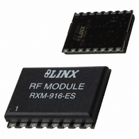
RXM-916-ES_
Description
RECEIVER RF 916MHZ 16PIN SMD
Manufacturer
Linx Technologies Inc
Series
-r
Specifications of RXM-916-ES_
Frequency
916MHz
Sensitivity
-102dBm
Data Rate - Maximum
56 kbps
Modulation Or Protocol
FM, FSK
Current - Receiving
6.5mA
Data Interface
PCB, Surface Mount
Antenna Connector
PCB, Surface Mount
Voltage - Supply
4.5 V ~ 5.5 V
Operating Temperature
0°C ~ 70°C
Package / Case
16-SMD
Board Size
20.6 mm x 16 mm x 3.2 mm
Minimum Operating Temperature
0 C
Supply Voltage (min)
4.5 V
Product
RF Modules
Maximum Frequency
916.48 MHz
Supply Voltage (max)
5.5 V
Maximum Operating Temperature
+ 70 C
Applications
-
Memory Size
-
Features
-
Lead Free Status / RoHS Status
Lead free / RoHS Compliant
Features
-
Applications
-
Memory Size
-
Lead Free Status / Rohs Status
Lead free / RoHS Compliant
Other names
RXM-916-ES
RXM-916-ES
RXM916ES
RXM-916-ES
RXM916ES
Available stocks
Company
Part Number
Manufacturer
Quantity
Price
Company:

Part Number:
RXM-916-ES_
Manufacturer:
LNX
Quantity:
49


USING THE RXM-***-ES FOR ANALOG APPLICATIONS
Figure 10: ES Series Receiver Squelch Circuit
Page 8
5k
POT
The ES Series is an excellent choice for sending a wide range of analog
information, including audio. The ability of the ES to receive combinations of
analog and digital signals also opens new areas of opportunity for creative
product design.
The transmission may contain simple or complex analog signals within the
specified audio bandwidth. Signal sources ranging from a single frequency to
complex content, such as audio, are handled with ease.
The AUDIO line of the receiver should be buffered and filtered to obtain
maximum signal quality. This is particularly important because the audio output
is AC-coupled, which means any DC loading will cause errors in the data slicer
since data is derived from the audio voltage. For voice, a 3-4kHz low-pass filter
is often employed. For broader-range sources, such as music, a 12-20kHz cutoff
may be more appropriate. When only sending audio, the DATA line should be
pulled to V
The Signal-to-Noise Ratio (SNR) of the audio will depend on the bandwidth you
select. The higher the SNR, the less hiss you will hear in the background. For
the best SNR, choose the lowest filter cutoff appropriate for the intended signal.
For applications that require true high fidelity, audio RF links designed expressly
for this purpose may prove to be a more appropriate solution; however, a
compandor may also be used with the ES Series transmitter to provide further
SNR improvements.
The 360mV
so an amplifier will be required. This amplifier can also be used to provide the
buffering and filtering described above. Some manufacturers make amplifiers
specifically for audio applications, but standard filter designs, such as
Butterworth or Sallen-Key, can also be used with success.
To avoid audible white noise or hiss when no transmission is present, a squelch
circuit can be implemented to provide muting. This is easily accomplished with a
circuit like the one shown below.
GND
Analog squelching is implemented by comparing the RSSI voltage to a voltage
reference (typically a voltage divider) with an open collector-style comparator.
When the RSSI voltage becomes lower than the voltage reference, the
comparator output is pulled to ground, disabling the AUDIO output. This is useful
because the analog circuit can be disabled either when the receiver is out of
range or the transmitter is turned off. Of course it is the designer’s responsibility
to choose a squelch topology that best fits the specific needs of the product.
10k
RSSI
CC
P-P
to reduce noise resulting from the data slicer switching.
output level of the AUDIO line is not sufficient to drive a speaker,
39k
GND
2M
VCC
GND
39k
0.01uF
–
+
LM393
10-20k
AUDIO REF
USING THE ES FOR DIGITAL APPLICATIONS
Figure 11: ES Series Receiver Squelch / Hysteresis Circuit
GND
10k
5k
As previously discussed, it is important to note that this receiver does not provide
hysteresis or squelching of the DATA line. This means that in the absence of a
valid transmission or transitional data, the DATA line will switch randomly. In
many applications this hash will be ignored by the decoder or system software,
but, depending on your application, it may be useful to add an external circuit to
provide data squelching and hysteresis.
A squelch circuit will disable the DATA output when the RSSI voltage falls below
a reference level. Hysteresis will make the RSSI voltage have to fall lower than
the reference voltage before switching off, and to have to rise higher than the
reference voltage before switching on. This will prevent low amplitude noise from
causing the data line to switch, reducing hash during times that the transmitter is
off or during transmitter steady-state times exceeding 5mS. Strong signals can
still get through, so it is a good idea to have a noise tolerant protocol.
Creating a circuit that has additional hysteresis characteristics is very basic and
requires very few parts thanks to the A REF line. All you need is a couple of
resistors to provide some isolation for the AUDIO and A REF lines, a large
feedback resistor, a pull-up resistor, and an open collector comparator.
The RSSI and A REF lines allow a wide variety of squelch circuits to be
implemented. One such possibility is the circuit below, which is used on the ES
Series Master Development System, and may be employed for audio or data
squelching. It is ultimately the responsibility of the designer to determine what, if
any, circuit would be most appropriate for the needs of the product.
Data squelching in the circuit above is accomplished by comparing the RSSI
voltage to a voltage reference (typically a voltage divider) with an open collector
style comparator. When the voltage from the RSSI becomes lower than the
voltage reference, the comparator output is pulled to GND. This is useful
because this output can be used to disable the data-slicer circuit either when the
receiver is out of range or the transmitter is turned off.
The squelch threshold will normally be set as low as possible to ensure
maximum sensitivity and range. It is important to recognize that in many actual
use environments, ambient noise and interference may enter the receiver at
levels well above the squelch threshold. For this reason, it is always
recommended that the product’s protocol be structured to allow for the possibility
of hashing even when an external squelch circuit is employed.
RSSI
39k
GND
2M
GND
VCC
39k
0.01uF
GND
1
3
4
LM393
OUTA
INA-
INA+
GND
390k
VCC
8
VCC VCC
10k
2M
10k
10k
Qualified Data
AUDIO REF
AUDIO
Page 9
Related parts for RXM-916-ES_
Image
Part Number
Description
Manufacturer
Datasheet
Request
R

Part Number:
Description:
RECEIVER 433MHZ LR SERIES
Manufacturer:
Linx Technologies Inc
Datasheet:

Part Number:
Description:
RECEIVER 418MHZ LR SERIES
Manufacturer:
Linx Technologies Inc
Datasheet:

Part Number:
Description:
RECEIVER 315MHZ LR SERIES
Manufacturer:
Linx Technologies Inc
Datasheet:

Part Number:
Description:
RECEIVER RF 869MHZ 16PIN SMD
Manufacturer:
Linx Technologies Inc
Datasheet:

Part Number:
Description:
RECEIVER RF 900MHZ 8-CH PACK
Manufacturer:
Linx Technologies Inc
Datasheet:

Part Number:
Description:
RECEIVER RF 900MHZ 8PAR/120SRLCH
Manufacturer:
Linx Technologies Inc
Datasheet:

Part Number:
Description:
MODULE USB LOW SPEED
Manufacturer:
Linx Technologies Inc
Datasheet:

Part Number:
Description:
IC TRANSCODER MT BI-DIR 20-SSOP
Manufacturer:
Linx Technologies Inc
Datasheet:

Part Number:
Description:
IC ENCODER LOW SECURITY 8DIP
Manufacturer:
Linx Technologies Inc
Datasheet:

Part Number:
Description:
IC DECODER MS SERIES 20-SSOP
Manufacturer:
Linx Technologies Inc
Datasheet:
Part Number:
Description:
IC ENCODER MS SERIES 20-SSOP
Manufacturer:
Linx Technologies Inc
Datasheet: