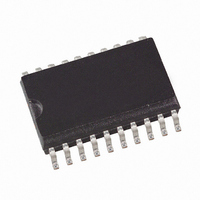
T5744N-TK Atmel, T5744N-TK Datasheet - Page 7

T5744N-TK
Manufacturer Part Number
T5744N-TK
Description
IC RCVR300-450MHZ UHF ASK 20SSOP
Manufacturer
Atmel
Datasheet
1.T5744N-TK.pdf
(19 pages)
Specifications of T5744N-TK
Frequency
300MHz ~ 450MHz
Sensitivity
-108dBm
Modulation Or Protocol
ASK
Applications
General Purpose Data Transmission Systems
Current - Receiving
30mA
Data Interface
PCB, Surface Mount
Antenna Connector
PCB, Surface Mount
Voltage - Supply
4.5 V ~ 5.5 V
Operating Temperature
-40°C ~ 105°C
Package / Case
20-SSOP
Lead Free Status / RoHS Status
Contains lead / RoHS non-compliant
Features
-
Memory Size
-
Data Rate - Maximum
-
Other names
T5744-TKS
T5744-TKS
T5744-TKS
ASK Demodulator and
Data Filter
4521B–RKE–01/03
Figure 7. RSSI Characteristics
The signal coming from the RSSI amplifier is converted into the raw data signal by the
ASK demodulator.
An automatic threshold control circuit (ATC) is employed to set the detection reference
voltage to a value where a good signal-to-noise ratio is achieved. This circuit also
implies the effective suppression of any kind of inband noise signals or competing trans-
mitters. If the S/N ratio exceeds 10 dB, the data signal can be detected properly.
The output signal of the demodulator is filtered by the data filter before it is fed into the
digital signal processing circuit. The data filter improves the S/N ratio as its passband
can be adopted to the characteristics of the data signal. The data filter consists of a 1st-
order highpass and a 1st-order lowpass filter.
The highpass filter cut-off frequency is defined by an external capacitor connected to Pin
CDEM. The cut-off frequency of the highpass filter is defined by the following formula:
Recommended values for CDEM are given in the electrical characteristics.
The cut-off frequency of the lowpass filter is defined by the selected baudrate range
(BR_Range). BR_Range is defined by the Pins BR_0 and BR_1. BR_Range must be
set in accordance to the used baudrate.
Each BR_Range is defined by a minimum and a maximum edge-to-edge time (tee_sig).
These limits are defined in the electrical characteristics. They should not be exceeded to
maintain full sensitivity of the receiver.
fcu_DF
=
BR_1
------------------------------------------------- -
2
0
0
1
1
´
3.0
2.8
2.6
2.4
2.2
2.0
1.8
1.6
1.4
1.2
1.0
p
-130.0
´
R
1
1
´
CDEM
105°C
-110.0
25°C
T
-90.0
amb
= 40°C
P
Ref
BR_0
min.
(dBm)
0
1
0
1
-70.0
max.
-50.0
-30.0
BR_Range
0
1
2
2
T5744
7


