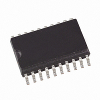
ATA5743P6-TKQY Atmel, ATA5743P6-TKQY Datasheet - Page 12

ATA5743P6-TKQY
Manufacturer Part Number
ATA5743P6-TKQY
Description
IC RCVR ASK/FSK 600KHZ 20SSOP
Manufacturer
Atmel
Datasheet
1.ATA5743P3-TGQY.pdf
(43 pages)
Specifications of ATA5743P6-TKQY
Frequency
300MHz ~ 450MHz
Sensitivity
-110dBm
Data Rate - Maximum
10 kBaud
Modulation Or Protocol
ASK, FSK
Applications
RKE, Telemetering, Security Technology
Current - Receiving
7.5mA
Data Interface
PCB, Surface Mount
Antenna Connector
PCB, Surface Mount
Voltage - Supply
4.5 V ~ 5.5 V
Operating Temperature
-40°C ~ 105°C
Package / Case
20-SOIC (0.300", 7.50mm Width)
Operating Frequency (max)
450000kHz
Operating Temperature (min)
-40C
Operating Temperature (max)
105C
Operating Temperature Classification
Industrial
Product Depth (mm)
4.4mm
Operating Supply Voltage (min)
4.5V
Operating Supply Voltage (typ)
5V
Operating Supply Voltage (max)
5.5V
Lead Free Status / RoHS Status
Lead free / RoHS Compliant
Features
-
Memory Size
-
Lead Free Status / Rohs Status
Compliant
6.2
6.3
12
Polling Mode
Sleep Mode
ATA5743
As shown in
three different modes. In sleep mode, the signal processing circuitry is disabled for the time
period T
nal processing circuits are enabled and settled. In the following bit-check mode, the incoming
data stream is analyzed bit-by-bit, looking for a valid transmitter signal. If no valid signal is
present, the receiver is set back to sleep mode after the period T
check-by-check as it is a statistical process. An average value for T
cal characteristics. During T
condition of the receiver is indicated on pin IC_ACTIVE.
The average current consumption in polling mode is dependent on the duty cycle of the active
mode and can be calculated as:
During T
reception of a transmitted command, the transmitter must start the telegram with an adequate
preburst. The required length of the preburst depends on the polling parameters T
T
on the actual bit rate and the number of bits (N
The following formula indicates how to calculate the preburst length.
T
The length of period T
sion factor X
be:
T
In US and European applications, the maximum value of T
to “1”; the time resolution is about 2 ms in that case. The sleep time can be extended to almost
half a second by setting X
As seen in
permanent sleep condition. The receiver remains in that condition until another value for Sleep is
programmed into the OPMODE register. This function is desirable where several devices share
a single data line and may also be used for microcontroller polling – via pin POLLING/_ON, the
receiver can be switched on and off.
I
Spoll
Bit-check
Preburst
Sleep
= Sleep
=
, and the start-up time of a connected microcontroller (T
Sleep
I
--------------------------------------------------------------------------------------------------------------- -
Sleep
Soff
T
Sleep
Table 6-7 on page
Figure 6-2 on page
Sleep
while consuming low current of I
and T
T
+ T
T
X
Sleep
Sleep
(see
Sleep
Startup
Startup
Sleep
+
+
Table 6-8 on page
I
Son
T
, the receiver is not sensitive to a transmitter signal. To guarantee the
+ T
1024
Sleep
Startup
is defined by the 5-bit word Sleep of the OPMODE register, the exten-
Bit-check
Startup
to 8. X
T
26, the highest register value of sleep sets the receiver into a
13, the receiver’s polling mode consists of a continuous cycle of
+
Startup
T
Clk
T
+ T
Bit-check
and T
Sleep
Start_
+
T
can be set to 8 by setting bit X
26), and the basic clock cycle T
Bit-check
µ
Bit-check
C
S
Bit-check
= I
Soff
, the current consumption is I
. During the start-up period, T
) to be tested.
Sleep
Start,
is about 60 ms if X
Bit-check
µ
Bit-check
C
). Thus, T
SleepStd
is given in the electri-
Clk
. This period varies
. It is calculated to
to “1”.
Bit-check
4839B–RKE–08/05
S
Startup
Sleep
= I
Sleep
depends
Son
, T
, all sig-
Startup
. The
is set
,


