MRX-001-433DR-B Radios Inc, MRX-001-433DR-B Datasheet - Page 5
MRX-001-433DR-B
Manufacturer Part Number
MRX-001-433DR-B
Description
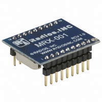
MODULE RECEIVER 433MHZ 18DIP
Manufacturer
Radios Inc
Datasheet
1.MRX-001-433DR-B.pdf
(10 pages)
Specifications of MRX-001-433DR-B
Frequency
433MHz
Sensitivity
-95dBm
Data Rate - Maximum
4.8 kbps
Modulation Or Protocol
AM, OOK
Applications
Garage Openers, RKE, Security Alarms
Current - Receiving
10mA
Data Interface
PCB, Through Hole
Antenna Connector
Through Hole
Voltage - Supply
5 V ~ 16 V
Operating Temperature
0°C ~ 70°C
Package / Case
18-DIP Module
Lead Free Status / RoHS Status
Contains lead / RoHS non-compliant
Features
-
Memory Size
-
Other names
694-1000


UHF AM RECEIVER MODULE
MRX-001
1,2,3,13,14
4,5,6,7,8
DIP
18
17
16
15
12
11
10
9
Pin Number
Surface Mount
7,8,9,14,15
2,3,4,5,6
10
11
12
13
16
17
18
1
MRX-001, 433.92MHz Fixed, 1200bps Bandwidth
Typical Application Schematic
Programmable Bandwidth Configurations
REG-EN In a regulated module, this pin powers on the module with a 2-
1
2
3
4
5
6
7
8
9
*Note: 1=VCC, 0=GND
SWEN Controls the operating mode of the receiver. When high, the
Name
SEL0
SEL1
SEL0
+VIN
Gnd
+5V
N/C
Pin
Ant
DO
0
1
0
1
N/C
N/C
N/C
GND
GND
GND
GND
GND
ANT
MRX-001
MRX-001
This is the receive RF input, internally ac-coupled. Connect this
pin to the receive antenna.
Ground
No Connect
Output data pin. CMOS level compatible.
receiver is in sweep mode.When low, the module operates as a
conventional single-conversion superheterodyne receiver (fixed
mode) - this is the recommended mode of operation. This pin is
internally pulled-up to VCC.
Programs desired Demodulator Filter Bandwidth. This pin is
internally pulled-up to VCC. See Table 1.
Programs desired Demodulator Filter Bandwidth. This pin is
internally pulled-up to VCC. See Table 1.
16V supply input. Pulling this pin low disables module. In a non-
regulated module, this is a no connect.
In a regulated module, this is a 5V output from the onboard
regulator when REG-EN is high (2-16V). In a non-regulated
module, this is the 4.75V to 5.5V power supply input.
In a regulated module, this is the power supply pin of the module.
Input 5-16V to power a regulated module. In a non-regulated
module, this is a no connect.
SEL1
REG-EN
Pin Detail
SWEN
0
0
1
1
SEL1
SEL0
+VIN
Table 1
+5V
N/C
N/C
DO
-Page 5-
18
17
16
15
14
13
12
11
10
Bandwidth (bps)
Data Out to MCU
GND
GND
+5V
+2V-16V In
+5V Output
+5V-16V In
1200
2400
4800
600
Description
MCU
Related parts for MRX-001-433DR-B
Image
Part Number
Description
Manufacturer
Datasheet
Request
R

Part Number:
Description:
XMITTER HANDHELD 433MHZ 2BUTTON
Manufacturer:
Radios Inc
Datasheet:
Part Number:
Description:
XMITTER HANDHELD 915MHZ 2BUTTON
Manufacturer:
Radios Inc
Datasheet:

Part Number:
Description:
MODULE RCVR REM CTRL RADIOS INC.
Manufacturer:
Radios Inc
Datasheet:


Part Number:
Description:
MODULE RCVR REMOTE CTRL KEELOQ
Manufacturer:
Radios Inc
Datasheet:
Part Number:
Description:
MODULE RCVR REMOTE CTRL HOLTEK
Manufacturer:
Radios Inc
Datasheet:
Part Number:
Description:
XMITTER HANDHELD 433MHZ 2BUTTON
Manufacturer:
Radios Inc
Datasheet:
Part Number:
Description:
XMITTER HANDHELD 433MHZ 2BUTTON
Manufacturer:
Radios Inc
Datasheet:
Part Number:
Description:
XMITTER HANDHELD 915MHZ 2BUTTON
Manufacturer:
Radios Inc
Datasheet:
Part Number:
Description:
XMITTER HANDHELD 915MHZ 2BUTTON
Manufacturer:
Radios Inc
Datasheet:

Part Number:
Description:
MODULE RECEIVER 433MHZ 18DIP
Manufacturer:
Radios Inc
Datasheet:

Part Number:
Description:
MODULE RECEIVER 433MHZ 18DIP
Manufacturer:
Radios Inc
Datasheet: