AA003041-G Navman Wireless, AA003041-G Datasheet - Page 10
AA003041-G
Manufacturer Part Number
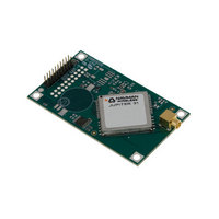
AA003041-G
Description
MODULE JUPITER 31 GPS W/R/A OSX
Manufacturer
Navman Wireless
Specifications of AA003041-G
Frequency
1.575GHz
Sensitivity
-159dBm
Modulation Or Protocol
GPS
Applications
GPS
Data Interface
Connector, 2 x 10 Header, 2 mm Pitch
Antenna Connector
OSX
Voltage - Supply
3.3V
Operating Temperature
-40°C ~ 85°C
Package / Case
Module
Lead Free Status / RoHS Status
Lead free / RoHS Compliant
Features
-
Memory Size
-
Data Rate - Maximum
-
Current - Receiving
-
Other names
943-1007


4.0 Electrical requirements
All parameters specified in this section are based on room temperature conditions (22 ± 2°C) and
a typical power supply voltage (3.3 ± 0.1 V or
4.1 Power supply
LA010811B © 2008 Navman Wireless OEM Solutions. All rights reserved. Proprietary information and specifications subject to change without notice.
4.1.1 Primary power
The Jupiter 31 GPS receiver is designed to operate from a single supply voltage, meeting the
requirements shown in Table 4-1.
4.1.2 Battery backup (SRAM/RTC backup)
During ‘powered down’ conditions, the SRAM and RTC (Real Time Clock) may be kept
operating by supplying power from the VBATT as shown in Table 5-2.
4.1.3 Low supply voltage detector
The module will enter a reset mode if the main supply drops below 3.0 V.
4.1.4 RF (Radio Frequency) input
RF input is 1575.42 MHz (L1 Band) at a level between –135 dBm and –159 dBm into a 50 Ω
impedance. This input may have a DC voltage impressed upon it to supply power to an active
antenna. The maximum input return loss is –9 dB.
4.1.5 Antenna gain
The receiver will operate with a passive antenna with unity gain. However, GPS performance
will be optimum when an active antenna is used. The gain of an active antenna at the input of
the module is ideally 16 dB.
4.1.6 Burnout protection
The receiver accepts without risk of damage a signal of +10 dBm from 0 to 2 GHz carrier
frequency, except in band 1560 to 1590 MHz where the maximum level is –10 dBm.
4.1.7 Jamming performance
The jamming performance of the receiver based upon a 3 dB degradation in C/N
performance is shown in Table 4-2. This is with reference to the external antenna. These
results are determined using a CW (Continuous Wave) Jammer.
input voltage
average sustained power
(after 1st solution)
average sustained acquisition
power (before 1st solution)
average initial acquisition power
(1.5–2 s)
power (typ) using ATP*
battery backup voltage**
battery backup current
ripple
*Using Adaptive TricklePower with a 1 s update
**Battery backup voltage must not fall below 2.5 V
CAUTION! If battery backup is not used, the Jupiter 31 receiver will revert to default
settings if power is removed.
Parameter
Table 4-1: Operating power for the
not to exceed 50 mV peak
2.85 to 6.0 VDC
80 mW at 3.3 V
5 to 6 µA (typ)
5.0 ± 0.1 V
<136 mW
<149 mW
<189 mW
3.3 VDC
to peak
Value
) unless otherwise stated.
Jupiter 31
not to exceed 50 mV peak to
2.85 to 6.0 VDC
80 mW at 3.3 V
5 to 6 µA (typ)
<250 mW
<275 mW
<300 mW
5.0 VDC
Value
peak
0
10
Related parts for AA003041-G
Image
Part Number
Description
Manufacturer
Datasheet
Request
R

Part Number:
Description:
ANTENNA GPS ACTIVE 5M CABLE
Manufacturer:
Navman Wireless
Datasheet:

Part Number:
Description:
DEV KIT FOR JUPITER 32XLP
Manufacturer:
Navman Wireless
Datasheet:

Part Number:
Description:
DEV KIT FOR JUPITER 30XLP
Manufacturer:
Navman Wireless
Datasheet:

Part Number:
Description:
DEV KIT FOR JUPITER 3 AND J3-30
Manufacturer:
Navman Wireless
Datasheet:

Part Number:
Description:
TERMINAL MDT-860 MOBILE DATA
Manufacturer:
Navman Wireless
Datasheet:


Part Number:
Description:
MODULE GPS RECEIVER JUPITER 3
Manufacturer:
Navman Wireless
Datasheet:

Part Number:
Description:
MODULE GPS JUPITER 30XLP 20CH
Manufacturer:
Navman Wireless
Datasheet:

Part Number:
Description:
MODULE GPS JUPITER 32XLP 20CH
Manufacturer:
Navman Wireless
Datasheet:

Part Number:
Description:
MODULE GPS RECEIVER JUPITER 3-30
Manufacturer:
Navman Wireless
Datasheet:

Part Number:
Description:
MODULE GPS RECEIVER JUPITER 2
Manufacturer:
Navman Wireless
Datasheet:

Part Number:
Description:
DEV KIT FOR MDT860
Manufacturer:
Navman Wireless
Datasheet:

Part Number:
Description:
EVAL KIT GPS JUPITER 2
Manufacturer:
Navman Wireless
Datasheet: