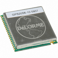
GM-205610-000 DeLorme, GM-205610-000 Datasheet - Page 6

GM-205610-000
Manufacturer Part Number
GM-205610-000
Description
MODULE GPS RCVR GPS2056-10
Manufacturer
DeLorme
Specifications of GM-205610-000
Frequency
1.575GHz
Data Rate - Maximum
57.6 kbps
Modulation Or Protocol
GPS
Applications
GPS Receiver
Current - Receiving
50mA
Data Interface
PCB, Surface Mount
Antenna Connector
PCB, Surface Mount
Voltage - Supply
3 V ~ 3.6 V
Operating Temperature
-40°C ~ 85°C
Package / Case
40 Pin
Lead Free Status / RoHS Status
Lead free / RoHS Compliant
Features
-
Sensitivity
-
Memory Size
-
Other names
GM-205610-000TR
GPS Software
The GPS2056-10 ROM code includes the GPS software release 4.30.3+PAL. The SBAS software (release 1.6) has been also
added; it is ON by default and can be deactivated via a software commands (see below).
Software Configuration
GPIO used for software configuration
To increase flexibility, some general purposes pins have been used to configure the software. The configuration values are read
only one time at each system restart, just before the GPS startup, so after this period they can assume any other value. The
GPIO involved have been configured as IN/OUT pins and an internal weak pull-up/ pull-down has been set on each one to have
a default configuration pattern. The GPIO can be left unconnected if the default software configuration does not need to be
modified. Care should be exercised on the configuration pin patterns at the startup time if the same pins are used for any other
purpose (e.g. connecting the pin to a different device and drive it using a software command). If the configuration needs to be
modified, external pull-up/pull-down resistors must be placed on the right pins.
The list below summarizes each pin/port number, associated function and default value.
NMEA message configuration
Using the BAUD pin two different sets of GPS NMEA out messages, with two different baud rates can be selected.
Pins Configured by Software
One pin is configured by software to drive a 3DFix led. This pin can be also configured by a software command to switch OFF
the led functionality and enable the Clock Out, to allow a bus clock measurement.
External Serial Flash Memory Configuration
Starting with ROM software version 4.30.3+PAL an external serial (SPI) memory is supported to store the GPS backup data
(refer to the dedicated section for further details). Three different memories can be used: M95128 (EEPROM), M25P10 (1
Mbit FLASH) and M25P40 (4Mbit FLASH). To configure the software to address the installed memory type, two GPIO pins have
been used as listed in the table below:
Port
TRACKLED
(GPIO P0_12)
PO_2
Leave unconnected /
external pull-up
Leave unconnected /
external pull-up
External pull-down
External pull-down
Pin/Port
Number
P0_14
SBAS/P1_7
BAUD/P0_13
Leave unconnected / external pull-up
External pull-down
Description
Reserved - Drivers of this pin should be Tri-stated until NMEA Messages Start
Reserved - Drivers of this pin should be Tri-stated until NMEA Messages Start
Description
3DFix led: in normal conditions, this pin is able to drive a led to flag the GPS 3DFix availability.
Led ON means the 3DFix is available, led OFF means the fix is not available.
PO_7
Leave unconnected /
external pull-up
External pull-down
Leave unconnected /
external pull-up
External pull-down
NMEA Messages Set
Msg_list : GGA5 - VTG - GSA - GSV
Baud Rate: 4800
Debug_mode: DEBUG_ON
Transmit mode: ON_UTC_SECOND
Msg_list : GGA5 - GSA - GSV - RMC - TG - TS - PA
Baud Rate: 57600
Debug_mode: DEBUG_ON
Transmit mode: ON_UTC_SECOND
Description
External flash memory
is not available
M25P10 FLASH
is available
M95128 EEPROM
is available
M25P40 FLASH
is available
Default
X
Default
Default
Configuration Value
Internal Weak Pull-up
Internal Weak Pull-up
X
Page 6


