MICRF011BN Micrel Inc, MICRF011BN Datasheet - Page 7
MICRF011BN
Manufacturer Part Number
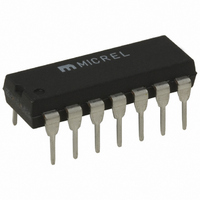
MICRF011BN
Description
IC RCVR/DATA DEMOD RF/IF 14DIP
Manufacturer
Micrel Inc
Datasheet
1.MICRF011YM.pdf
(11 pages)
Specifications of MICRF011BN
Frequency
300MHz ~ 440MHz
Sensitivity
-103dBm
Data Rate - Maximum
10 kbps
Modulation Or Protocol
OOK
Applications
Garage Openers
Current - Receiving
2.4mA
Data Interface
PCB, Surface Mount
Antenna Connector
PCB, Surface Mount
Features
Automatic Tuning
Voltage - Supply
4.75 V ~ 5.5 V
Operating Temperature
-40°C ~ 85°C
Package / Case
14-DIP (0.300", 7.62mm)
Operating Band Frequency
300 to 440MHz
Operating Temperature (min)
-40C
Operating Temperature (max)
85C
Operating Temperature Classification
Industrial
Operating Supply Voltage (min)
4.75V
Operating Supply Voltage (typ)
5V
Operating Supply Voltage (max)
5.5V
Lead Free Status / RoHS Status
Contains lead / RoHS non-compliant
Memory Size
-
Lead Free Status / Rohs Status
Not Compliant


MICRF011
Functional Description
Please refer to “MICRF011 Block Diagram”. Identified in the
figure are the three principal functional blocks of the IC,
namely (1) UHF Downconverter, (2) OOK Demodulator, and
(3) Reference and Control. Also shown in the figure are two
capacitors (CTH, CAGC) and one timing component (CR),
usually a ceramic resonator. With the exception of a supply
decoupling capacitor, these are all the external components
needed with the MICRF011 to construct a complete UHF
receiver.
diagram, SEL0, SEL1 and SWEN.
inputs the user can control the operating mode and
programmable functions of the IC. These inputs are CMOS
compatible, and are pulled-up on the IC.
Input SWEN selects the operating mode of the IC (FIXED
mode or SWP mode). When low, the IC is in FIXED mode,
and functions as a conventional superheterodyne receiver.
When SWEN is high, the IC is in SWP mode. In this mode,
while the topology is still superheterodyne, the local
oscillator (LO) is deterministically swept over a range of
frequencies at rates greater than the data rate.
coupled with a peak-detecting demodulator, this technique
effectively increases the RF bandwidth of the MICRF011, so
the device can operate in applications where significant
Transmitter/Receiver frequency misalignment may exist.
[Note:
bandwidth, so noise performance is not impacted relative to
FIXED mode. In other words, the IF bandwidth is the same
(500kHz) whether the device is in FIXED or SWP mode.]
Due to limitations imposed by the LO sweeping process, the
upper limit on data rate in SWP mode is approximately
2.5kbps. Data rates beyond 10kbps are possible in FIXED
mode however.
Examples of SWP mode operation include applications
which utilize low-cost LC-based transmitters, whose transmit
frequency may vary up to
aging, and temperature. In this (patent-pending) mode, the
LO frequency is varied in a prescribed fashion which results
in downconversion of all signals in a band approximately
1.5% around the transmit frequency.
may drift up to
Receiver, and without impacting system performance. Such
performance is not achieved with currently available crystal-
based superheterodyne receivers, which can operate only
with SAW or crystal based transmitters.
[Note: In SWP mode only, a range penalty will occur in
installations where there exists a competing signal of
sufficient strength in this small frequency band of 1.5%
around the transmit frequency. This results from the fact
that sweeping the LO indiscriminately “sweeps” all signals
within the sweep range down into the IF band. This same
penalty also exists with super-regenerative type receivers,
as their RF bandwidth is also generally 1.5%.
application for a super-regenerative receiver is also an
application for the MICRF011 in SWP mode.]
For applications where the transmit frequency is accurately
set for other reasons (e.g., applications where a SAW
December 1998b
The swept LO technique does not affect the IF
Three control inputs are shown in the block
0.5% without the need to retune the
0.5% over initial tolerance,
Through these logic
So the Transmitter
So any
When
QwikRadio
77
transmitter is used for its mechanical stability), the user may
choose to configure the MICRF011 as a standard
superheterodyne receiver (FIXED mode), mitigating the
aforementioned problem of a competing close-in signal.
This can be accomplished by tying SWEN to ground. Doing
so forces the on-chip LO frequency to a fixed value. In
FIXED mode, the ceramic resonator would be replaced with
a crystal.
operated in SWP mode, using a ceramic resonator, with
either LC or CRYSTAL/SAW based transmitters, without
any significant range difference.
The inputs SEL0 and SEL1 control the Demodulator filter
bandwidth in four binary steps (625Hz-5000Hz in SWP,
1250Hz-10000Hz in FIXED mode), and the user must select
the bandwidth appropriate to his needs.
Rolloff response of the IF Filter is 5
demodulator data filter exhibits a 2
Multiplication factor between the REFOSC frequency ft and
the internal Local Oscillator (LO) is 64.5X for FIXED mode,
and 64.25X for SWP mode (i.e., for ft = 6.00MHz in FIXED
mode, LO frequency = 6.00MHz * 64.5 = 387MHz).
Slicing Level and the CTH Capacitor
Extraction of the DC value of the demodulated signal for
purposes of logic-level data slicing is accomplished by
external capacitor CTH and the on-chip switched-cap
“resistor” RSC, indicated in the block diagram. The effective
resistance of RSC is 118kohms.
CTH is easily calculated, once the slicing level time-constant
is chosen. Values vary somewhat with decoder type, data
pattern, and data rate, but typical Slicing Level time
constants range 5-50msec. Optimization of the CTH value
is required to maximize range, as discussed in “Application
Note 22, MICRF001 Theory of Operation”, section 6.4.
During quiet periods (i.e., no signal transmissions) the Data
Output (DO pin) transitions randomly based on noise. This
may present problems for some decoders.
common solution is to introduce a small offset (“Squelch”)
on the CTH pin so that noise does not trigger the internal
comparator.
introduced by connecting a several-Megohm resistor from
the CTH pin to either VSS or VDD, depending on the desired
offset polarity. Since the MICRF011 is an AGC’d receiver,
noise at the internal comparator input is always the same,
set by the AGC. So the squelch offset requirement does not
change as the local “ether” noise changes from installation
to installation.
range modestly, so only introduce an amount sufficient to
“quiet” the output.
AGC Function and the CAGC Capacitor
The signal path has automatic gain control (AGC) to
increase input dynamic range.
CAGC, must be connected to the CAGC pin of the device.
The ratio of decay-to-attack time-constant is fixed at 10:1
(i.e., the attack time constant is 1/10th the decay time
constant), and this ratio cannot be changed by the user.
However, the attack time constant is selectable by the user
through the value of capacitor CAGC.
tm
Generally, however, the MICRF011 can be
Usually 20-30mV is sufficient, and may be
Note that introducing squelch will reduce
The value of capacitor
An external capacitor,
nd
th
order, while the
order response.
MICRF011
Micrel
The most
Related parts for MICRF011BN
Image
Part Number
Description
Manufacturer
Datasheet
Request
R


Part Number:
Description:
MICR CTL LP 1K 4MHZ OTP ET 18DIP
Manufacturer:
Microchip Technology
Datasheet:

Part Number:
Description:
Manufacturer:
Micrel Inc
Datasheet:
Part Number:
Description:
Manufacturer:
Micrel Inc
Datasheet:
Part Number:
Description:
Manufacturer:
Micrel Inc
Datasheet:
Part Number:
Description:
Manufacturer:
Micrel Inc
Datasheet:
Part Number:
Description:
Manufacturer:
Micrel Inc
Datasheet:
Part Number:
Description:
Manufacturer:
Micrel Inc
Datasheet:
Part Number:
Description:
Manufacturer:
Micrel Inc
Datasheet:
Part Number:
Description:
Manufacturer:
Micrel Inc
Datasheet:
Part Number:
Description:
Manufacturer:
Micrel Inc
Datasheet:
Part Number:
Description:
Manufacturer:
Micrel Inc
Datasheet:
Part Number:
Description:
Manufacturer:
Micrel Inc
Datasheet:
Part Number:
Description:
Manufacturer:
Micrel Inc
Datasheet: