BMI-S-203-F Laird Technologies, BMI-S-203-F Datasheet - Page 23
BMI-S-203-F
Manufacturer Part Number
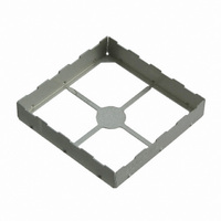
BMI-S-203-F
Description
BOARD SHIELD 1.032X1.032" FRAME
Manufacturer
Laird Technologies
Type
Framer
Specifications of BMI-S-203-F
Length - Overall
1.032" (26.21mm)
Width - Overall
1.032" (26.21mm)
Height - Overall
0.2" (5.08mm)
Mounting Type
Solder
Lead Free Status / RoHS Status
Lead free / RoHS Compliant
Other names
903-1052-2
BMI-S-203-F
BMI-S-203-F
Available stocks
Company
Part Number
Manufacturer
Quantity
Price
Company:

Part Number:
BMI-S-203-F
Manufacturer:
SILICON
Quantity:
2 300
Company:
Part Number:
BMI-S-203-F
Manufacturer:
LAIRD
Quantity:
2 100


MULTI-COMPARTMENTAL SHIELD DESIGN
Shield Multiple Circuit Groups Save PCB Space and Production Time
Printed circuit boards with multiple circuit groups pose unique design
challenges . Shielding these groups separately adversely affects circuit board
real estate and increases part count . Multi-compartmental shields allow
replacement of three or more single shields with one shield divided into
several walled compartments . Installing a single part reduces part count,
along with production time through faster pick-and-place speeds . This allows
for a reduction the number of parts in inventory, which lowers overhead
costs .
Multi-compartmental shields feature internal dividing walls of one material
thickness and meet all on-board shield requirements for FCC, VDE, CISPR
and CE . These shields are available in two-piece designs, either assembled
or unassembled . Our unassembled versions allow for automatic optical
inspection prior to cover placement . As in all our shielding offerings, Laird
Technologies proprietary process for 100% automatic optical inspection
verifies co-planarity including inner walls .
EZ PEEL
Economical Access for Low Incidences of Repairs
In cases where there is a low incidence of repairable circuit defects, access
may be needed to shielded components . An economical solution is EZ Peel
shields . These one-piece shields feature an easy-to-remove top section that
can be peeled back using simple tools for access to components . Built-in
flexibility controls the ease of removing the top, and the robust design
delivers superior flatness . EZ Peel shields are designed to accept a snap-on
cover in the same manner as our two-piece shields, following circuit repair .
DRAWN BOARD LEVEL SHIELDS
Seamless Corners Address High-Frequency Leakage
As microprocessor speeds continue to increase, so does the potential for
EMI leakage through the smallest apertures in board level shields . Laird
Technologies drawn board level shields are designed to provide additional
near-field and far-field circuit isolation (attenuation) at higher frequencies
by eliminating the apertures found in the corners of traditional board level
solutions . Drawn board level shields utilize small ground trace sizes, thereby
preserving space on the circuit board .
•
•
•
required at higher frequencies
dimensions from .300" (7,6 mm) to 2 .0" (50,8 mm)
attachment method
Solid corner designs when additional circuit isolation (attenuation) is
Available in custom heights up to .250" (6,4 mm) with length and width
Tape and reel packaging provides an economical and automated SMT
TM
SHIELD DESIGN
CUSTOM DESIGN SHIELDS AND CONTACTS
^
Near-Field is 2 . 0 " and 0 . 1 90", respectfully, from the transmit antenna . This test is performed
for worst case orientation .
Circuit Isolation is a measurement that defines the resultant attenuation level in dB provided
by a PCB shield from an initial reference level as defined in Laird test procedure PDA-PRO-
027 .
Notice: The data set forth in all text, tables, charts, graphs and figures herein are based on samples tested and are
not guaranteed for all samples or applications . Such data are intended as guides and do not reflect product
specification for any specific part .
•
•
•
•
Available in cold rolled steel, brass, stainless steel and nickel silver
Available with an EZ Peel scored cover feature; allows for easy top
section removal for component repair and re-sealing
Ventilation holes as needed for solder outgassing .
Molded Compartment Shields and Form-In-Place elastomers can be
combined with drawn board level shields to achieve shielding of
multiple components with a single part
The receive antenna test region from 1 GHz to 10 GHz that defines the Far-Field and
www.lairdtech.com 21
Series 97-2100
Related parts for BMI-S-203-F
Image
Part Number
Description
Manufacturer
Datasheet
Request
R

Part Number:
Description:
BOARD SHIELD .476X.538" FRAME
Manufacturer:
Laird Technologies
Datasheet:

Part Number:
Description:
BOARD SHIELD .65X.65" FRAME
Manufacturer:
Laird Technologies
Datasheet:

Part Number:
Description:
BOARD SHIELD 1.0X1.5" FRAME
Manufacturer:
Laird Technologies
Datasheet:

Part Number:
Description:
BOARD SHIELD 1.26X1.26" FRAME
Manufacturer:
Laird Technologies
Datasheet:

Part Number:
Description:
BOARD SHIELD 1.747X1.747" FRAME
Manufacturer:
Laird Technologies
Datasheet:

Part Number:
Description:
BOARD SHIELD 1.326X1.45" FRAME
Manufacturer:
Laird Technologies
Datasheet:

Part Number:
Description:
BOARD SHIELD 1.201X1.732" FRAME
Manufacturer:
Laird Technologies
Datasheet:

Part Number:
Description:
BOARD SHIELD .476X.538" 1PIECE
Manufacturer:
Laird Technologies
Datasheet:

Part Number:
Description:
BOARD SHIELD .65X.65" 1PIECE
Manufacturer:
Laird Technologies
Datasheet:

Part Number:
Description:
BOARD SHIELD 1.032X1.032" 1PIECE
Manufacturer:
Laird Technologies
Datasheet:

Part Number:
Description:
BLUETOOTH EVAL BOARD BTM511
Manufacturer:
Laird Technologies
Datasheet:

Part Number:
Description:
Bluetooth / 802.15.1 Modules & Development Tools BLUETTH Multimed MODLE, No ANT DEVKIT
Manufacturer:
Laird Technologies
Datasheet:

Part Number:
Description:
Bluetooth Serial Module Development Kit
Manufacturer:
Laird Technologies