MRF24J40MA-I/RM Microchip Technology, MRF24J40MA-I/RM Datasheet - Page 5
MRF24J40MA-I/RM
Manufacturer Part Number
MRF24J40MA-I/RM
Description
MODULE RF TXRX PICTAIL PLUS
Manufacturer
Microchip Technology
Datasheet
1.MRF24J40MA-IRM.pdf
(30 pages)
Specifications of MRF24J40MA-I/RM
Frequency
2.4GHz
Data Rate - Maximum
250kbps
Modulation Or Protocol
802.15.4
Applications
ISM, ZigBee™
Power - Output
0dBm
Sensitivity
-94dBm
Voltage - Supply
2.4 V ~ 3.6 V
Current - Receiving
19mA
Current - Transmitting
23mA
Data Interface
PCB, Surface Mount
Antenna Connector
On-Board, Trace
Operating Temperature
-40°C ~ 85°C
Package / Case
Module
Wireless Frequency
2.4 GHz
Interface Type
4-Wire SPI
Output Power
+ 3 dBm
Operating Supply Voltage
3.3 V
Maximum Operating Temperature
+ 85 C
Mounting Style
SMD/SMT
Minimum Operating Temperature
- 40 C
Modulation
OQPSK
Frequency Range
2.405GHz To 2.48GHz
Data Rate Max
250Kbps
Module Interface
SPI, 4-Wire
Supply Voltage Range
2.4V To 3.6V
Supply Current
23mA
Operating Temperature Range
-40°C To +85°C
Rohs Compliant
Yes
Sensitivity (dbm)
-94dBm
Lead Free Status / RoHS Status
Lead free / RoHS Compliant
Memory Size
-
Lead Free Status / Rohs Status
Lead free / RoHS Compliant
Other names
MRF24J40MA
MRF24J40MA
MRF24J40MA
Available stocks
Company
Part Number
Manufacturer
Quantity
Price
Company:

Part Number:
MRF24J40MA-I/RM
Manufacturer:
MICROCHIP
Quantity:
12 000


1.0
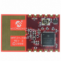
The MRF24J40MA is a 2.4 GHz IEEE Std. 802.15.4™
compliant, surface mount module with integrated
crystal, internal voltage regulator, matching circuitry
and PCB antenna. The MRF24J40MA module oper-
ates in the non-licensed 2.4 GHz frequency band and
is FCC, IC and ETSI compliant. The integrated module
design frees the integrator from extensive RF and
antenna design, and regulatory compliance testing,
allowing quicker time to market.
The
Microchip’s ZigBee
stacks. Each software stack is available as a free
download, including source code, from the Microchip
web site http://www.microchip.com/wireless.
The MRF24J40MA module has received regulatory
approvals for modular devices in the United States
(FCC), Canada (IC) and Europe (ETSI). Modular
approval removes the need for expensive RF and
antenna design and allows the end user to place the
FIGURE 1-1:
© 2008 Microchip Technology Inc.
MRF24J40MA
DEVICE OVERVIEW
Antenna
PCB
®
, MiWi™ and MiWi P2P software
MRF24J40MA BLOCK DIAGRAM
module
Matching
Circuitry
MRF24J40MA IEEE Std. 802.15.4™ Module
is
compatible
Physical
with
MRF24J40
MRF24J40MA module inside a finished product and
not require regulatory testing for an intentional radiator
(RF
Approval” for specific requirements to be followed by
the integrator.
1.1
Figure 1-1 shows a simplified block diagram of the
MRF24J40MA module. The module is based on the
Microchip Technology MRF24J40 IEEE 802.15.4™
2.4 GHz RF Transceiver IC. The module interfaces to
many popular Microchip PIC
4-wire serial SPI interface, interrupt, wake, Reset,
power and ground, as shown in Figure 1-2. Table 1-1
provides the pin descriptions.
Data communications with the MRF24J40MA module
are documented in the “MRF24J40 IEEE 802.15.4™
2.4 GHz RF Transceiver Data Sheet” (DS39776). Refer
to the MRF24J40 Data Sheet for specific serial
interface protocol and register definitions.
MAC
20 MHz
Crystal
transmitter).
Interface Description
Management
Interface
Power
MRF24J40MA
See
Section 3.0
®
microcontrollers via a
SPI
DS70329B-page 3
“Regulatory
Digital
Power
I/O
Related parts for MRF24J40MA-I/RM
Image
Part Number
Description
Manufacturer
Datasheet
Request
R

Part Number:
Description:
IC TXRX IEEE/ZIGBEE 2.4GHZ 40QFN
Manufacturer:
Microchip Technology
Datasheet:

Part Number:
Description:
IEEE 802.15.4� 2.4 GHz RF Transceiver
Manufacturer:
MICROCHIP [Microchip Technology]
Datasheet:

Part Number:
Description:
Ieee 802.15.4? 2.4 Ghz Rf Transceiver
Manufacturer:
Microchip Technology Inc.
Datasheet:
Part Number:
Description:
Manufacturer:
Microchip Technology Inc.
Datasheet:
Part Number:
Description:
Manufacturer:
Microchip Technology Inc.
Datasheet:
Part Number:
Description:
Manufacturer:
Microchip Technology Inc.
Datasheet:
Part Number:
Description:
Manufacturer:
Microchip Technology Inc.
Datasheet:
Part Number:
Description:
Manufacturer:
Microchip Technology Inc.
Datasheet:
Part Number:
Description:
Manufacturer:
Microchip Technology Inc.
Datasheet:
Part Number:
Description:
Manufacturer:
Microchip Technology Inc.
Datasheet: