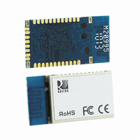
RN-42 Roving Networks Inc, RN-42 Datasheet - Page 8

RN-42
Manufacturer Part Number
RN-42
Description
MODULE BLUETOOTH V2.1+EDR
Manufacturer
Roving Networks Inc
Series
RNr
Specifications of RN-42
Frequency
2.4GHz
Data Rate - Maximum
3Mbps
Modulation Or Protocol
Bluetooth v2.1+EDR, Class 2 & 3
Applications
General Purpose
Power - Output
2dBm
Sensitivity
-80dBm
Voltage - Supply
3 V ~ 3.6 V
Current - Receiving
25mA
Current - Transmitting
25mA
Data Interface
PCB, Surface Mount
Antenna Connector
On-Board, Chip
Operating Temperature
-40°C ~ 85°C
Package / Case
Packaged Unit
Wireless Frequency
2.4 GHz
Data Rate
1200 bps to 921 Kbps
Modulation
FHSS, GFSK
Operating Voltage
3.3 V
Antenna
Chip
Operating Temperature Range
- 40 C to + 85 C
Output Power
2 dBm
Technology/ Type
Class 2 Bluetooth Module
Lead Free Status / RoHS Status
Lead free / RoHS Compliant
Memory Size
-
Lead Free Status / Rohs Status
Lead free / RoHS Compliant
Other names
740-1038
Available stocks
Company
Part Number
Manufacturer
Quantity
Price
Company:
Part Number:
RN-42-EK
Manufacturer:
CONEXANT
Quantity:
320
Company:
Part Number:
RN-42-SM
Manufacturer:
MICROCHIP
Quantity:
101
Design Concerns
1. Reset circuit. RN-42 contains a weak pullup to VCC, the polarity of reset on the RN42 is ACTIVE LOW.
2. Factory reset PIO4. It is a good idea to connect this pin to a switch, or jumper, or resistor, so it can be
3. Connection status. PIO5 is available to drive an LED, and blinks at various speeds to indicate status.
4. HCI mode. The RN42 module must be loaded with special firmware to run in HCI mode. When in HCI
5. Using SPI bus for flash upgrade. While not required, this bus is very useful for configuring advanced
6. Minimizing Radio interference. When laying out the carrier board for the RN42 module the areas under
A power on reset circuit with delay is OPTIONAL on the reset pin of the module. It should only be required
if the input power supply has a very slow ramp, or tends to bounce or have instability on power up.
a microcontroller or embedded CPU IO is available to generate reset once power is stable. If not, there
are many low cost power supervisor chips available, such as MCP809, MCP102/121, and Torex XC61F.
accessed. This pin can be used to reset the module to FACTORY DEFAULTS and is often critical in
situations where the module has been mis-configured. To set Factory defaults start HIGH, then toggle two
times.
PIO2 is an output which directly reflects the connection state, it goes HIGH when connected, and LOW
otherwise.
mode the standard SPP/DUN applications are disabled.
parameters of the Bluetooth modules, and is required for upgrading the firmware on modules. The
suggested ref-design shows a 6pin header which can be implemented to gain access to this bus. A
minimum-mode version could just use the SPI signals (4pins) and pickup ground and VCC from elsewhere
on the design.
the antenna and shielding connections should not have surface traces, GND planes, or exposed vias.
(See diagram to right) For optimal radio performance the antenna end of RN42 module should protrude
5mm past any metal enclosure.
809 University Avenue
www.rovingnetworks.com
Do not locate any
plane under the
tr aces, inter nal
tr aces or GND
ATTENTION:
par ts, sur face
antenna ar ea
•
Los Gatos, CA 95032
1.5 mm
1.5 mm
7.0 mm
10
11
12
1
2
3
4
5
6
7
8
9
35 34
~ 8 ~
vias or sur face
1.5m m squar e
•
29 33
ATTENTION:
Do not locate
tr aces under
connector s
1.5 mm
Tel (408) 395-6539
13.2 mm
shield
RN-42/RN-42-N Data Sheet
32
31
28
30
24
23
22
21
20
19
18
17
16
15
14
13
• info@RovingNetworks.com
1.5 mm
DS-RN42-V3.1 12/6/2010
25.8 mm
2.0 mm
Often


