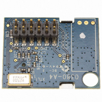
AWA24S Artaflex Inc, AWA24S Datasheet - Page 2

AWA24S
Manufacturer Part Number
AWA24S
Description
MODULE POWER AMPLIFIER
Manufacturer
Artaflex Inc
Series
WirelessUSB™r
Datasheet
1.AWA24S.pdf
(15 pages)
Specifications of AWA24S
Frequency
2.4GHz
Data Rate - Maximum
1Mbps
Modulation Or Protocol
DSSS, GFSK
Applications
Wireless Modules
Power - Output
-5dBm ~ 20dBm
Sensitivity
-93dBm
Voltage - Supply
2.5 V ~ 3.6 V
Current - Receiving
23mA
Current - Transmitting
195mA
Data Interface
Connector, 2 x 6 Header, 2mm Pitch
Antenna Connector
On-Board, Chip
Operating Temperature
0°C ~ 70°C
Package / Case
Module
Lead Free Status / RoHS Status
Lead free / RoHS Compliant
Memory Size
-
Other names
748-1003
Available stocks
Company
Part Number
Manufacturer
Quantity
Price
Company:
Part Number:
AWA24S
Manufacturer:
Artaflex Inc
Quantity:
135
4
The AWA24S Module provides a complete SPI to RF antenna wireless MODEM. The module is designed to implement wireless
device links operating in the worldwide 2.4-GHz ISM frequency band. It is intended for systems compliant with world-wide
regulations covered by Europe ETSI EN 301 489-1, ETSI EN 301 489-7, & ETSI EN 300 328-1, USA FCC Part 15 and Industry
Canada RSS-210 standards.
The module contains a 2.4-GHz 1-Mbps GFSK radio transceiver, packet data buffering, packet framer, DSSS baseband controller,
Received Signal Strength Indication (RSSI), and SPI interface for data transfer and device configuration.
The radio supports 60 discrete 1-MHz channels. In DSSS modes the baseband performs DSSS spreading/de-spreading, while in
GFSK Mode (1 Mb/s - GFSK) the baseband performs Start of Frame (SOF), End of Frame (EOF) detection and CRC16 generation
and checking.
When in receive mode, with packet framing enabled, the device is always ready to receive data transmitted at any of the supported
bit rates, except SDR, enabling the implementation of mixed-rate systems in which different devices use different data rates. This
also enables the implementation of dynamic data rate systems, which use high data rates at shorter distances and/or in a low-
moderate interference environment, and change to lower data rates at longer distances and/or in high interference environments.
4.1
The AWA24S module supports the following data packet framing features:
SOP – Packets begin with a 2-symbol Start of Packet (SOP) marker. This is required in GFSK and 8DR modes, but is optional in
DDR mode and is not supported in SDR mode; if framing is disabled then an SOP event is inferred whenever two successive
correlations are detected. The SOP_CODE_ADR code used for the SOP is different from that used for the “body” of the packet and
if desired may be a different length. SOP must be configured to be the same length on both sides of the link.
EOP – There are two options for detecting the end of a packet. If SOP is enabled, then a packet length field may be enabled.
GFSK and 8DR must enable the length field. This is the first 8-bits after the SOP symbol, and is transmitted at the payload data
rate. If the length field is enabled, an End of Packet (EOP) condition is inferred after reception of the number of bytes defined in the
length field, plus two bytes for the CRC16 (if enabled—see below). The alternative to using the length field is to infer an EOP
condition from a configurable number of successive non-correlations; this option is not available in GFSK mode and is only
recommended to enable when using SDR mode.
CRC16 – The device may be configured to append a 16-bit CRC16 to each packet. The CRC16 uses the USB CRC polynomial
with the added programmability of the seed. If enabled, the receiver will verify the calculated CRC16 for the payload data against
the received value in the CRC16 field. The starting value for the CRC16 calculation is configurable, and the CRC16 transmitted
may be calculated using either the loaded seed value or a zero seed; the received data CRC16 will be checked against both the
configured and zero CRC16 seeds.
CRC16 detects the following errors:
4.2
All data transmission and reception utilizes the 16-byte packet buffers—one for transmission and one for reception.
The transmit buffer allows a complete packet of up to 16-bytes of payload data to be loaded in one burst SPI transaction, and then
transmitted with no further micro controller intervention. Similarly, the receive buffer allows an entire packet of payload data up to
16 bytes to be received with no firmware intervention required until packet reception is complete.
The AWA24S module supports packet length of up to 40 bytes; interrupts are provided to allow a micro controller to use the
transmit and receive buffers as FIFOs. When transmitting a packet longer than 16 bytes, the micro controller can load 16-bytes
initially, and add further bytes to the transmit buffer as transmission of data creates space in the buffer. Similarly, when receiving
packets longer than 16 bytes, the micro controller must fetch received data from the FIFO periodically during packet reception to
prevent it from overflowing.
Artaflex Inc.
Markham, Ontario, Canada
L3R8T9
905-479-0148
215 Konrad Crescent
•
•
•
•
Any one bit in error
Any two bits in error (no matter how far apart, which column, and so on)
Any odd number of bits in error (no matter where they are)
An error burst as wide as the checksum itself
Functional Overview
Link Layer Modes
Packet Buffers
2.4GHz Radio Module with Integrated Power Amplifier
Page 2 of 15
http://www.artaflexmodules.com
Revised October 6, 2008
DSAWA24S Rev 2v6
Data Sheet
AWA24S


