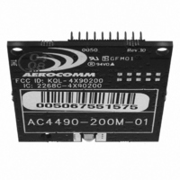
AC4490-200M Laird Technologies, AC4490-200M Datasheet - Page 44

AC4490-200M
Manufacturer Part Number
AC4490-200M
Description
TXRX 900MHZ 3.3-5.5V TTL 200MW
Manufacturer
Laird Technologies
Series
AeroCommr
Specifications of AC4490-200M
Frequency
902MHz ~ 928MHz
Data Rate - Maximum
115.2kbps
Modulation Or Protocol
FHSS, FSK
Applications
AMR, Fire & Security Alarms, Telemetry
Power - Output
5mW ~ 200mW
Sensitivity
-110dBm
Voltage - Supply
3.3V, 5V
Current - Transmitting
68mA
Data Interface
Connector, 2 x 10 Header
Antenna Connector
MMCX
Operating Temperature
-40°C ~ 85°C
Package / Case
Module
Output Power
200 mW
Antenna
Integral and External Dipole
Lead Free Status / RoHS Status
Contains lead / RoHS non-compliant
Memory Size
-
Current - Receiving
-
Lead Free Status / Rohs Status
Lead free / RoHS Compliant
Other names
AC4490-200M-01
EEPROM P
The OEM Host can program various parameters that are stored in EEPROM which become active after a power-on
reset. The table below gives the locations and descriptions of the parameters that can be read/written by the OEM
Host. Factory default values are also shown. Do not write to any EEPROM addresses other than those listed below.
Do not copy one transceiver’s EEPROM to another transceiver as doing so may cause the transceiver to malfunction.
Product ID
Range Refresh
Stop Bit Delay
Channel Number
Server/Client Mode
Baud Rate Low
Baud Rate High
Control 0
Frequency Offset
Parameter
0x00
0x3D
0x3F
0x40
0x41
0x42
0x43
0x45
0x46
EEPROM
Address
ARAMETERS
40
1
1
1
1
1
1
1
1
Length
(Bytes)
T a b l e 1 6 : E E P R O M P a r a m e t e r s
0x01 -
0xFF
0x00 -
0xFF
0x00 -
0x37
0x01 -
0x02
0x00 -
0xFF
0x00
0x00 -
0xFF
0x00 -
0xFF
www.aerocomm.com
Range
0x18
0xFF
1x1: 0x00
200: 0x00
1000: 0x10
0x02
0xFC
0x00
0x14
0x01
Default
Description
40 bytes - Product identifier string. Includes revision informa-
tion for software and hardware.
Specifies the maximum amount of time a transceiver will
report In Range without having heard a Server’s beacon
(equal to hop period * value). Do not set to 0x00.
For systems employing the RS-485 interface or Parity, the
serial stop bit might come too early. Stop bit delay controls
the width of the last bit before the stop bit occurs.
0xFF = Disable Stop Bit Delay (12 us)
0x00 = (256 * 1.6 us) + 12 us
0x01 - 0xFE = (value * 1.6 us) + 12 us
Set 0 = 0x00 - 0x0F (US/Canada): 1x1/200
Set 1 = 0x10 - 0x2F (US/Canada): 1x1/1000
Set 2 = 0x30 - 0x37 Australia: 1x1/200/1000
0x01 = Server
0x02 = Client
Low byte of the interface baud rate. Default baud rate is
57,600.
High byte of interface baud. Always 0x00.
Settings are:
bit-7: One Beacon Mode
bit-6: DES Enable
bit-5: Sync to Channel
bit-4: Aerocomm Use Only
bit-3: Aerocomm Use Only
bit-2: Aerocomm Use Only
bit-1: RF Delivery
bit-0: Aerocomm Use Only
Protocol parameter used in conjunction with Channel Num-
ber to satisfy unique regulations.
0 = Disable One Beacon Mode
1 = Enable One Beacon Mode
0 = Disable Encryption
1 = Enable Encryption
0 = Disable Sync to Channel
1 = Enable Sync to Channel
0 = Transmit using Addressed packets
1 = Transmit using Broadcast packets
9


