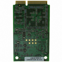
20-101-1265 Rabbit Semiconductor, 20-101-1265 Datasheet - Page 37

20-101-1265
Manufacturer Part Number
20-101-1265
Description
MODULE MINICORE RCM5600W
Manufacturer
Rabbit Semiconductor
Series
MiniCore™r
Datasheet
1.101-1285.pdf
(130 pages)
Specifications of 20-101-1265
Frequency
2.4GHz
Modulation Or Protocol
802.11 b/g
Applications
General Purpose
Voltage - Supply
3.15 V ~ 3.45 V
Current - Receiving
625mA
Current - Transmitting
625mA
Data Interface
Connector, Mini PCI express
Memory Size
1 MB Flash, 1MB SRAM
Antenna Connector
U.FL
Operating Temperature
-30°C ~ 55°C
Package / Case
Module
Wireless Frequency
2.4 GHz
Security
64/128 bit WEP
Operating Voltage
3.3 V
Antenna
U.FL Connector
Operating Temperature Range
- 30 C to + 55 C
Lead Free Status / RoHS Status
Lead free / RoHS Compliant
Power - Output
-
Sensitivity
-
Data Rate - Maximum
-
Lead Free Status / Rohs Status
Lead free / RoHS Compliant
For Use With/related Products
Rabbit 5000
Other names
316-1174
4.2 Serial Communication
The RCM5600W board does not have any serial level converters directly on the board.
However, an Ethernet or other serial interface may be incorporated on the board the
RCM5600W is mounted on. For example, the Serial Communication accessory board in
the Deluxe Development Kit has an RS-232 transceiver, and the Interface Board has USB
connections.
4.2.1 Serial Ports
There are six serial ports designated as Serial Ports A, B, C, D, E, and F. All six serial
ports can operate in an asynchronous mode up to the baud rate of the system clock divided
by 8. An asynchronous port can handle 7 or 8 data bits. A 9th bit address scheme, where
an additional bit is sent to mark the first byte of a message, is also supported.
Serial Port A is normally used as a programming port, but may be used either as an asyn-
chronous or as a clocked serial port once application development has been completed and
the RCM5600W is operating in the Run Mode.
Serial Port B, shared by the RCM5600W module’s serial flash and by the A/D converter in
the Wi-Fi circuit, is set up as a clocked serial port. Since this serial port is set up for syn-
chronous serial communication, you will lose the peripheral functionality if you try to use
the serial port in the asynchronous mode.
Serial Ports C and D can also be operated in the clocked serial mode. In this mode, a clock
line synchronously clocks the data in or out. Either of the two communicating devices can
supply the clock.
Serial Ports E and F can also be configured as SDLC/HDLC serial ports. The IrDA proto-
col is also supported in SDLC format by these two ports. Serial Ports E and F must be con-
figured before they can be used. The following macros show one way to do this.
OEM User’s Manual
#define SERE_TXPORT PEDR
#define SERE_RXPORT PEDR
#define SERF_TXPORT PFDR
#define SERF_RXPORT PFDR
NOTE: Since Serial Port B is shared, exercise care if you attempt to use Serial Port B for
other serial communication. Your application will have to manage the sharing negotia-
tions to avoid conflicts when reading or writing to the devices already using Serial Port B.
Any conflict with Serial Port B while the RCM5600W is powering up may prevent an
application from loading from the serial flash when the RCM5600W powers up or resets.
Do not drive or load the Serial Port B or SCLKB (PC4, PC5, and PB0) pins while the
RCM5600W is powering up. The serial port B pins should not be reallocated for general
purpose I/O.
31


