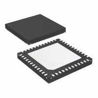
ATA5423-PLQW Atmel, ATA5423-PLQW Datasheet - Page 89

ATA5423-PLQW
Manufacturer Part Number
ATA5423-PLQW
Description
IC TXRX WIDEBAND 315MHZ 48QFN
Manufacturer
Atmel
Specifications of ATA5423-PLQW
Frequency
315MHz
Data Rate - Maximum
20kbps
Modulation Or Protocol
ASK, FSK
Applications
Alarm, ISM, Telemetry
Power - Output
5dBm
Sensitivity
-112.5dBm
Voltage - Supply
2.4 V ~ 3.6 V or 4.4 V ~ 6.6 V
Current - Receiving
10.5mA
Current - Transmitting
10mA
Data Interface
PCB, Surface Mount
Antenna Connector
PCB, Surface Mount
Operating Temperature
-40°C ~ 85°C
Package / Case
48-VQFN Exposed Pad, 48-HVQFN, 48-SQFN, 48-DHVQFN
Operating Temperature (min)
-40C
Operating Temperature (max)
85C
Operating Temperature Classification
Industrial
Product Depth (mm)
7mm
Product Height (mm)
0.9mm
Product Length (mm)
7mm
Lead Free Status / RoHS Status
Contains lead / RoHS non-compliant
Memory Size
-
Lead Free Status / Rohs Status
Compliant
Other names
ATA5423-PLQH
ATA5423-PLQHTR
ATA5423-PLQHTR
ATA5423-PLQWTR
ATA5423-PLQHTR
ATA5423-PLQHTR
ATA5423-PLQWTR
15. Electrical Characteristics: Base-station Application (5V)
All parameters refer to GND and are valid for T
f
4841D–WIRE–10/07
RF
*) Type means: A = 100% tested, B = 100% correlation tested, C = Characterized on samples, D = Design parameter
11.10
11.11
11.1
11.2
11.3
11.4
11.5
11.6
11.7
11.8
11.9
No.
11
= 315 MHz/345 MHz/433.92 MHz/868.3 MHz/915 MHz unless otherwise specified.
Parameters
Base-station Application (5V)
Supported voltage
range
Power supply output
voltage
Supply voltage for
microcontroller
interface
Threshold hysteresis
Reset threshold
voltage at pin VSOUT
(N_RESET)
Reset threshold
voltage at pin VSOUT
(Low_Batt)
Current in IDLE mode
on pin VS2 and VAUX
Supply current in
IDLE mode
Current in RX mode
on pin VS2 and VAUX
Supply current in RX
mode
Current during
T
and VAUX
Startup_PLL
on pin VS2
-
V
Test Conditions
Base
application (5V)
Base
application (5V)
V
I
(3.25V regulator
mode, V_REG2, see
Figure 5-1 on page
30)
I
CLK enabled
V
CLK disabled
V
V
I
CLK enabled V
enabled
I
VSOUT
VSOUT
VSOUT
VSOUT
VS2
Thres_2
VSOUT
VSOUT
VSOUT
= V
-
-
station
station
= 0
= 0
= 0
enabled
enabled
disabled
–
VAUX
13.5 mA
V
amb
Thres_1
= 25°C, V
VSOUT
ATA5423/ATA5425/ATA5428/ATA5429
VS2
19, 27
17, 19
22, 27
17, 19
22, 27
17, 19
Pin
17,
17,
19,
17,
19,
22
27
22
22
22
= 5.0V. Application according to
I
I
Startup_PLL_VS2,
IDLE_VS2_VAUX
I
V
RX_VS2_VAUX
Symbol
VS2
V
V
V
V
I
S_IDLE
I
V
Thres_1
Thres_2
VAUX
VSOUT
S_RX
VSINT
, V
Thres
AUX
or I
or I
or I
I
RX_VS2,VAUX
Startup_PLL_VS2,VAUX
TX_VS2,VAUX
IDLE_VS2,VAUX
Min.
4.75
2.18
2.26
3.0
2.4
60
I
S_IDLE
I
S_RX
Figure 2.2 on page 8
Typ.
2.38
10.8
444
380
310
2.3
9.1
80
= I
= I
IDLE_VS2_VAUX
RX_VS2_VAUX
VAUX
VS2
Max.
5.25
5.25
2.42
14.5
100
580
500
400
3.5
2.5
12
+ I
+ I
VSINT
VSINT
Unit
mV
mA
mA
µA
V
V
V
V
V
+ I
+ I
EXT
EXT
Type*
C
A
A
A
B
A
A
B
B
89


