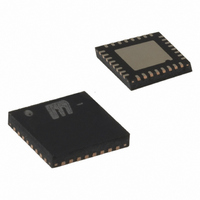
MICRF507YML TR Micrel Inc, MICRF507YML TR Datasheet - Page 20

MICRF507YML TR
Manufacturer Part Number
MICRF507YML TR
Description
TXRX FSK LOW PWR W/AMP 32MLF
Manufacturer
Micrel Inc
Series
RadioWire®r
Datasheet
1.MICRF507YML_TR.pdf
(46 pages)
Specifications of MICRF507YML TR
Frequency
470MHz ~ 510MHz
Data Rate - Maximum
200kbps
Modulation Or Protocol
FSK
Applications
AMR, ISM, SRD
Power - Output
10dBm
Sensitivity
-113dBm
Voltage - Supply
2 V ~ 2.5 V
Current - Receiving
12mA
Current - Transmitting
21.5mA
Data Interface
PCB, Surface Mount
Antenna Connector
PCB, Surface Mount
Operating Temperature
-40°C ~ 85°C
Package / Case
32-MLF®, QFN
Lead Free Status / RoHS Status
Lead free / RoHS Compliant
Memory Size
-
Other names
576-3694-2
MICRF507YML TRTR
MICRF507YML TRTR
MICRF507YMLTR
MICRF507YML TRTR
MICRF507YML TRTR
MICRF507YMLTR
Frequency Synthesizer
The MICRF507 frequency synthesizer is an integer-N
phase-locked loop consisting of:
The loop filter is external for flexibility and can be a
simple passive circuit.
The phase/frequency detector compares the reference
frequency (from the M-divider) with the VCO output fed
through the programmable frequency divider. The
charge pump output of the phase/frequency detector,
March 2010
Micrel, Inc.
•
•
•
•
a reference source, made of an M-divider
clocked by the crystal oscillator
a voltage controlled oscillator (VCO)
a programmable frequency divider made of an
N-divider, an A-divider, and a dual modulus
prescaler
a phase/frequency detector
Field Name
M0
A0
N0
M1
A1
N1
CP_HI
VCO_Freq
VCO_IB
LD_en
Number
of bits
Table 9. Register Bit Fields for Frequency Synthesizer
12
12
12
12
3
6
6
1
2
1
Location of bits
Reg13[3:0],
Reg11[3:0],
Reg18[3:0],
Reg16[3:0],
Reg14[7:0]
Reg10[5:0]
Reg12[7:0]
Reg19[7:0]
Reg15[5:0]
Reg17[7:0]
Reg3[1:0]
Reg3[4:2]
Reg2[7]
Reg1[2]
after filtering, controls the VCO, closing the loop and forcing
the error between the reference frequency and the divided
VCO frequency to zero.
The block diagram, Figure 12, shows the basic elements and
arrangement of a PLL-based frequency synthesizer. The
MICRF507 has a dual modulus prescaler for increased
frequency resolution. In a dual modulus prescaler the main
divider is split into two parts, the main part N and an
additional divider A, where A < N. Both dividers are clocked
from the output of the dual-modulus prescaler, but only the
output of the N divider is fed into the phase detector. The
prescaler will first divide by 16. Both N and A count down
until A reaches zero, at which point the prescaler is switched
to a division ratio 16+1. At this point, the divider N has
completed A counts. Counting continues until N reaches
zero, which is an additional N-A counts. At this point, the
cycle repeats.
Description
M0 counter
A0 counter
N0 counter
M1 counter
A1 counter
N1 counter
High charge pump current (1= 500μA, 0 = 125µA)
Frequency setting of VCO (see Table 11)
VCO bias current setting (see Table 11)
Lock detect function on/off
20
M9999-032210-B
MICRF507


