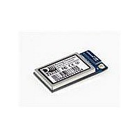
RN-131C Roving Networks Inc, RN-131C Datasheet - Page 5

RN-131C
Manufacturer Part Number
RN-131C
Description
MODULE WIFLY GSX 802.11 B/G U.FL
Manufacturer
Roving Networks Inc
Datasheet
1.RN-131G.pdf
(11 pages)
Specifications of RN-131C
Frequency
2.4GHz
Data Rate - Maximum
54Mbps
Modulation Or Protocol
802.11 b/g
Applications
General Purpose
Power - Output
18dBm
Sensitivity
-85dBm
Voltage - Supply
3 V ~ 3.7 V
Current - Receiving
40mA
Current - Transmitting
140mA
Data Interface
PCB, Surface Mount
Memory Size
8Mb Flash, 128kB RAM
Antenna Connector
On-Board, Chip, U.FL
Operating Temperature
0°C ~ 70°C
Package / Case
Module
Wireless Frequency
2.4 GHz
Modulation
CCK, DBPSK, DQPSK
Security
EAP, WPA, WPA2
Operating Voltage
3.3 V
Output Power
18 dBm
Antenna
Chip, U.FL Connector
Operating Temperature Range
- 30 C to + 85 C
Lead Free Status / RoHS Status
Lead free / RoHS Compliant
Lead Free Status / RoHS Status
Lead free / RoHS Compliant, Lead free / RoHS Compliant
Other names
740-1036
Available stocks
Company
Part Number
Manufacturer
Quantity
Price
Part Number:
RN-131C
Manufacturer:
MICROCHIP/微芯
Quantity:
20 000
Company:
Part Number:
RN-131C/RM
Manufacturer:
NXP
Quantity:
1 000
36-44
Pin
10
11
12
13
14
15
16
17
18
19
20
21
22
23
24
25
26
27
28
29
30
31
32
33
34
35
1
2
3
4
5
6
7
8
9
FORCE_AWAKE
3.3V-REG-OUT
NO CONNECT
SENSE-PWR
3.3V-REG-IN
SUPERCAP
www.rovingnetworks.com
EPC-ANT-A
EPC-ANT-B
SENSOR-6
SENSOR-4
SENSOR-5
SENSOR-7
SENSOR-1
SENSOR-2
SENSOR-3
SENSOR-0
VDD-BATT
Pin Description
SPI-MOSI
SPI-MISO
UART-RX
UART-TX
GPIO-13
GPIO-12
SPI-CLK
DMA-RX
809 University Avenue
DMA-TX
VDD-IN
GPIO-9
GPIO-8
GPIO-7
GPIO-6
GPIO-5
GPIO-4
RESET
Name
GND
GND
Sensor interface, analog input to module, 1.2V
Sensor interface, Analog input to module, 1.2V
Sensor interface, Analog input to module, 1.2V
Analog input to module, 1.2V
Module reset, Active Low, reference to VDD-BATT, 160 usec pulse
EPC port, RFID antenna A
EPC port, RFID antenna B
Balance center pin voltage on stacked super capacitors, Analog 3.3V
Force the module to wakeup, input to module, 250us min. pulse.3.3V
UART RTS flow control, 8mA drive, 3.3V tolerant
UART CTS flow control, 8mA drive, 3.3V tolerant
INPUT: RX in to the module, 3.3V tolerant
OUTPUT: TX out from the module, 8mA drive, 3.3V tolerant
SPI master data out (Contact Roving Networks for details)
SPI clock, (Contact Roving Networks for details)
SPI master data in (Contact Roving Networks for details)
boost regulator control output, connect to 3.3V-REG-IN to enable
boost regulator control input, connect to 3.3V-REG-OUT to enable
Ground
Battery input, 2.0-3.3V with boost regulator in use, 3.0-3.7V otherwise
3.3 to 3.7 voltage, do not connect when boost regulator is in use
Debug port
Debug port
Restore factory resets/Enter Adhoc mode, 8mA drive, 3.3V tolerant
GPIO, 24mA drive, 3.3V tolerant
GPIO, 24mA drive, 3.3V tolerant
Association STATUS, 24mA drive, 3.3V tolerant
Data transfer STATUS, 24mA drive, 3.3V tolerant
Connection STATUS, 24mA drive, 3.3V tolerant
Sensor interface, analog input to module, 1.2V
Sensor interface, analog input to module, 1.2V
Sensor interface, analog input to module, 1.2V
Voltage output from module to power external sensors, 3.3V
Wakeup from external condition
Must be connected for proper antenna performance
•
Los Gatos, CA 95032
*(apply 100K pulldown if ultra low sleep power reqd)
10
10
11
11
12
12
13
13
1
1
2
2
3
3
4
4
5
5
6
6
7
7
8
8
9
9
44 43 42 41 40 39 38 37 36
44 43 42 41 40 39 38 37 36
14 15 16 17 18 19 20 21 22
14 15 16 17 18 19 20 21 22
(pads not visible from top)
(pads not visible from top)
~ page 5 ~
Description
Top view
Top view
•
Tel (408) 395-6539
35
35
34
34
33
33
32
32
31
31
30
30
29
29
28
28
27
27
26
26
25
25
24
24
23
23
RN-131G & RN-131C
• info@RovingNetworks.com
RN-131-DS v2.5 12/2/2010
LED_YELLOW output
LED_GREEN output
LED_RED output
GND to disable
No connect
No connect
No connect
No connect
No connect
No connect
No connect
No connect
No connect
No connect
No connect
No connect
No connect
GP output
GP output
Default
HIGH Z
Pull up
INPUT


