RN-24S Roving Networks Inc, RN-24S Datasheet - Page 2
RN-24S
Manufacturer Part Number
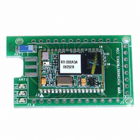
RN-24S
Description
SUPERMODULE BLUETOOTH CHIP ANT
Manufacturer
Roving Networks Inc
Specifications of RN-24S
Frequency
2.4GHz
Data Rate - Maximum
721kbps
Modulation Or Protocol
Bluetooth v2.0+EDR, Class 1 & 2
Applications
Bluetooth v2.0
Power - Output
4dBm
Sensitivity
-80dBm
Voltage - Supply
4 V ~ 24 V
Current - Receiving
40mA
Current - Transmitting
40mA
Data Interface
PCB, Surface Mount
Antenna Connector
On-Board, Chip
Package / Case
Module
Wireless Frequency
2.402 GHz to 2.48 GHz
Interface Type
UART
Data Rate
240 Kbps to 300 Kbps
Modulation
FHSS, GFSK
Operating Voltage
3.3 V
Antenna
Chip Antenna
Board Size
20.32 mm x 50.8 mm x 4.08 mm
Lead Free Status / RoHS Status
Lead free / RoHS Compliant
Operating Temperature
-
Memory Size
-
Lead Free Status / Rohs Status
Lead free / RoHS Compliant
Other names
740-1008


WARNING: take care not to exceed the voltage limits to the VCC, TTL SERIAL, and PIO pins.
0 negative voltage or voltage e xceeding 3.30VDC can permanently damage the device.
OPERATING MODES
0-Slave Mode - The default mode, other devices can discover and connect to the RN-24.
1 - Master Mode (SM,1<CR>) Enables outbound connections. To connect, use the “C” command.
2-Trigger Mode (SM,2<CR>) Automatically connects to stored address, when data is received on
local serial port of master.
3-Auto Master Mode (SM,3<CR>) Automatically connects to stored address on power up.
4-DTR Auto Master Mode (SM,4<CR>) Automatically connects/disconnects using PIO6 pin.
NOTE: In all master modes the device will not be discoverable or remote configurable.
LED
YELLOW LED
commands.
modes.
The RN-24 can communicate via serial port using either TTL (0-3.3V DC) or RS-232 Levels.
Factory default enables the on-board RS232 chip. To Disable RS-232 and use TTL pins,
remove resistor R7 located on the bottom side of the module, near the tab of the power regulator.
PIO Pins
These settings can be overridden by commands and the PIO pins can be used as general purpose
Input and output pins.
Roving Networks RN-24 V 4.22 5/31/2007
DATA INTERFACE
PIO
0
1
2
3
4
5
6
7
Connected
MODE
Boot up, Remote Configurable
Discoverable/Idle
Configuring
INPUT
INPUT
OUTPUT
INPUT
INPUT
INPUT
INPUT
OUTPUT
RED LED blinks when characters are received in command and slow data
is driven by PIO8 and can be turned ON and OFF with software
0
0
0
0
0
blinks
0
0
Powerup state
Not used
Not used
Goes high when connected
Auto discover mode when high
Factory reset when toggled 3 times
System status LED
Auto master mode/DTR mode when high
0=115K, 1=9600 default baudrate
GREEN LED BLINK
Fast, 10 x per second
2 times per second
1 time per second
On Solid
page 2
INSTANT CABLE REPLACEMENT EXAMPLE:
MASTER
1- PIO3 pulled High
2- PIO6 pulled High
Roving Networks RN-24 V 4.22 5/31/2007
1. Set PIO as shown above.
2.
3.
4.
Power up both devices
Master finds and store slave address, and auto connects.
Remove Pullup on PIO3 (so that they don’t try to re-pair each time power is
cycled).
SLAVE
1- PIO3 pulled High
page 7
Related parts for RN-24S
Image
Part Number
Description
Manufacturer
Datasheet
Request
R

Part Number:
Description:
ADAPTER BLUETOOTH FRFLY SRL FEML
Manufacturer:
Roving Networks Inc
Datasheet:

Part Number:
Description:
ADAPTER BLUETOOTH FRFLY SRL MALE
Manufacturer:
Roving Networks Inc
Datasheet:

Part Number:
Description:
ADAPTER BLUETOOTH FIREFLY RS422
Manufacturer:
Roving Networks Inc
Datasheet:

Part Number:
Description:
SUPERMODULE BLUETOOTH SMA JACK
Manufacturer:
Roving Networks Inc
Datasheet:

Part Number:
Description:
MODULE BLUETOOTH V2.1+EDR
Manufacturer:
Roving Networks Inc
Datasheet:

Part Number:
Description:
MODULE BLUETOOTH V2.1+EDR
Manufacturer:
Roving Networks Inc
Datasheet:

Part Number:
Description:
ANTENNA 2.4GHZ 4" SMA MALE
Manufacturer:
Roving Networks Inc
Datasheet:

Part Number:
Description:
ADAPTER BLUETOOTH 2.0 USB
Manufacturer:
Roving Networks Inc
Datasheet:

Part Number:
Description:
ADAPTER BLUETOOTH USB DRIVERLESS
Manufacturer:
Roving Networks Inc
Datasheet:

Part Number:
Description:
MODULE BLUETOOTH V2.0+EDR
Manufacturer:
Roving Networks Inc
Datasheet:

Part Number:
Description:
MODULE BLUETOOTH W/ANT CLASS1
Manufacturer:
Roving Networks Inc
Datasheet:

Part Number:
Description:
MODULE BLUETOOTH 2.0/EDR CLASS1
Manufacturer:
Roving Networks Inc
Datasheet:

Part Number:
Description:
MODULE BLUETOOTH AUDIO V1.2
Manufacturer:
Roving Networks Inc
Datasheet:

Part Number:
Description:
MODULE SOCKET BLUETOOTH CLASS1
Manufacturer:
Roving Networks Inc
Datasheet:
Part Number:
Description:
MODULE BLUETOOTH V2.1+EDR
Manufacturer:
Roving Networks Inc
Datasheet: