WSN802GP RFM, WSN802GP Datasheet

MODULE WLAN 802.11G 2.4GHZ TXRX

WSN802GP

Manufacturer Part Number
WSN802GP
Description
MODULE WLAN 802.11G 2.4GHZ TXRX
Manufacturer
RFM
Datasheets

Specifications of WSN802GP

Frequency
2.4GHz
Data Rate - Maximum
2Mbps
Modulation Or Protocol
802.11 b/g
Power - Output
10mW
Sensitivity
-92dBm
Voltage - Supply
3 V ~ 3.63 V
Current - Receiving
150mA
Current - Transmitting
200mA
Data Interface
PCB, Through Hole
Antenna Connector
U.FL
Operating Temperature
-40°C ~ 85°C
Package / Case
Module
Wireless Frequency
2.4 GHz
Interface Type
UART, SPI
Modulation
BPSK, QPSK
Security
802.1x, WPA2
Operating Voltage
3.3 V
Output Power
10 mW
Antenna
U.FL Coaxial
Operating Temperature Range
- 40 C to + 85 C
Lead Free Status / RoHS Status
Lead free / RoHS Compliant
Applications
-
Memory Size
-
Lead Free Status / Rohs Status
Lead free / RoHS Compliant
For Use With/related Products
WSN802G
Other names
583-1145
· Small Size, Light Weight, Low Cost
· 7.5 µA Sleep Current Supports Battery Operation
· Timer and Event Triggered Auto-reporting Capability
· Analog, Digital and Serial I/O for Sensor Applications
· -40 to +85
· FCC and ETSI Certified for Unlicensed Operation
The WSN802G transceiver module is a low cost, robust solution for 802.11g sensor
networks. The WSN802G’s very low sleep current makes long life battery operation
practical. The WSN802G module includes analog, digital and serial I/O, providing
the flexibility and versatility needed to serve a wide range of sensor network applica-
tions. The WSN802G module is easy to integrate and is compatible with standard
802.11b/g access points.
WSN802G Absolute Maximum Ratings
WSN802G Electrical Characteristics
www.RFM.com
©2009 by RF Monolithics, Inc.
Input/Output Pins Except ADC Inputs
ADC Input Pins
Non-Operating Ambient Temperature Range
Operating Frequency Range
Spread Spectrum Method
RF Chip Rate
RF Data Rates
Modulation Type
Number of RF Channels
RF Channel Spacing
Receiver Sensitivity, 8% PER:
RF Transmit Power
RF Connector
Optimum Antenna Impedance
1 Mb/s RF Data Rate
2 Mb/s RF Data Rate
o
C Operating Temperature Range
E-mail: info@rfm.com
Characteristic
Rating
Sym
-0.5 to +3.63
-0.5 to 1.98
-40 to +85
Value
Notes
Minimum
2401
Units
o
V
V
C
BPSK at 1 Mb/s, QPSK at 2 Mb/s
U.FL Coaxial Connector
CCK Direct Sequence
Typical
1 or 2
-92
-90
11
11
10
50
5
WSN802G
Wireless
Network
802.11g
Module
Sensor
DEVELOPMENT KIT
(Info
Maximum
Click
WSN802G - 04/29/09
2474
here)
Page 1 of 7
Units
MHz
Mc/s
Mb/s
MHz
dBm
dBm
mW
W

Related parts for WSN802GP

WSN802GP Summary of contents

Page 1

... RF Chip Rate RF Data Rates Modulation Type Number of RF Channels RF Channel Spacing Receiver Sensitivity, 8% PER: 1 Mb/s RF Data Rate 2 Mb/s RF Data Rate RF Transmit Power RF Connector Optimum Antenna Impedance www.RFM.com E-mail: info@rfm.com ©2009 by RF Monolithics, Inc. Value Units -0.5 to +3.63 V -0 -40 to +85 C Sym ...

Page 2

... Power Supply Voltage Range Power Supply Voltage Ripple Receive Mode Current Transmit Mode Current Sleep Mode Current WSN802GC Mounting WSN802GP Mounting Operating Temperature Range Operating Relative Humidity Range, Non-condensing CAUTION: Electrostatic Sensitive Device. Observe precautions when handling. www.RFM.com E-mail: info@rfm.com ©2009 by RF Monolithics, Inc. ...

Page 3

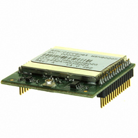
... PWM (DAC) output, two digital inputs and two digital out- puts to support sensor network applications. The WSN802G is available in two mounting configura- tions. The WSN802GC is designed for solder reflow mounting, and the WSN802GP is designed for plug-in connector mounting. www.RFM.com E-mail: info@rfm.com ©2009 by RF Monolithics, Inc. ...

Page 4

... RF ground for the WSN802GC only. Connect to the host circuit board ground plane. 29 RSVD - Reserved pin. Leave unconnected. 30 GND - RF ground for the WSN802GC only. Connect to the host circuit board ground plane. www.RFM.com E-mail: info@rfm.com ©2009 by RF Monolithics, Inc. Description WSN802G - 04/29/09 Page ...

Page 5

... Note that other circuit board traces should be spaced away from the stripline to prevent signal coupling, as shown in Figure 4. The stripline trace should be kept short to minimize its insertion loss. Figure 3 www.RFM.com E-mail: info@rfm.com ©2009 by RF Monolithics, Inc. Figure 2 Trace Separation from ...

Page 6

... E-mail: info@rfm.com ©2009 by RF Monolithics, Inc. Figure 5 Figure 6 Page WSN802G - 04/29/09 ...

Page 7

... Note: Specifications subject to change without notice. www.RFM.com E-mail: info@rfm.com ©2009 by RF Monolithics, Inc. Figure 7 Part # M-0802-1000, Rev A Page WSN802G - 04/29/09 ...

Related keywords