RN-111B-E Roving Networks Inc, RN-111B-E Datasheet
RN-111B-E
Specifications of RN-111B-E


Related parts for RN-111B-E


RN-111B-E Summary of contents
Page 1
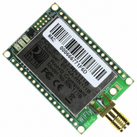
... WiFLy RN-111B 802.11b “wifi” wireless LAN – OEM Module Integration Guide and Users Manual Version 1.25 June 19, 2009 ...
Page 2
... RN-111B Overview ............................................................................................................ 3 2.1. RN-111B Features ....................................................................................................... 3 2.2. RN-111B Options ........................................................................................................ 3 2.3. RN-111B Specifications .............................................................................................. 4 2.4. RN-111B Block Diagram ............................................................................................ 4 2.5. RN-111B Electrical Characteristics ............................................................................. 5 2.6. RN-111B Operating and Environmental Conditions .................................................. 5 2.7. RN-111B Dimensions .................................................................................................. 6 2.8. RN-111B Pin Description ............................................................................................ 6 3. Introduction ........................................................................................................................ 7 3.1. Hardware Interface ...................................................................................................... 7 3.2. Configuration ............................................................................................................... 8 3.3. LED indications ........................................................................................................... 8 4 ...
Page 3
• • • • • • • • • • • • • • • • • • • • • • ...
Page 4
DSSS(CCK-11, CCK-5.5, DQPSK-2, DBPSK-1) ...
Page 5
≤ ≤ ...
Page 6
NOTE: Any unused pins should be left floating. ...
Page 7
... Warning: Do NOT exceed the voltage ratings on the 3.3V pins, damage to the module will result. • • • ...
Page 8
...
Page 9
...
Page 10
“set 2” ...
Page 11
“set u p e” ...
Page 12
...
Page 13
...
Page 14
...
Page 15
... Only the SENS1 input has a resistor divider ( 24K in series with 10K to GROUND) which allows this pin to tolerate 3V logic. The other sensor pins DO NOT, so care must be taken. WARNING: Under no conditions should the voltage on any SENS2-8 input exceed 1.2VDC. Permanent damage to the module will result. ...
Page 16
SENS1-4 pins that are not used should be left unconnected. When the module is ...
Page 17
... There are a number of print functions that can be enabled to assist in debugging the operation and status of the module. The following command is used to control these printouts. Bit Function 1 Print startup messages showing progress of association, dhcp, etc. Once the configuration has been checked, this can then be turned off so that these messages do not interfere with the datastream. ...
Page 18
...
Page 19
... WiFly contains a built in FTP client for getting files and updating the firmware. The client uses passive mode FTP, which allows operation thru firewalls and the Internet. There are 3 fixed settings that need to be used. The username is roving. The password is Pass123. The default directory is /public. ...
Page 20
• • • ...
Page 21
...
Page 22
...