DEMOKITCRX14 STMicroelectronics, DEMOKITCRX14 Datasheet - Page 19
DEMOKITCRX14
Manufacturer Part Number
DEMOKITCRX14
Description
RFID EVALUATION KIT ISO14443-B
Manufacturer
STMicroelectronics
Type
Development kitr
Specifications of DEMOKITCRX14
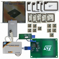
Contents
CD-ROM, CRX14 Board, USB Transceiver, Samples and Documentation
Processor To Be Evaluated
CRX14
Interface Type
I2C
Operating Supply Voltage
5 V
For Use With/related Products
CRX14
Lead Free Status / RoHS Status
Contains lead / RoHS non-compliant
Other names
497-3704
Available stocks
Company
Part Number
Manufacturer
Quantity
Price
Company:

Part Number:
DEMOKITCRX14
Manufacturer:
HITACHI
Quantity:
340


CRX14
4.6
Figure 7.
BUS Master
CRX14 WRITE
BUS Slave
CRX14 I²C write operations
The bus master sends a START condition, followed by a Device Select Code and the R/W
bit set to ’0’. The CRX14 that corresponds to the Device Select Code, acknowledges and
waits for the bus master to send the Byte address of the register that is to be written to. After
receipt of the address, the CRX14 returns another ACK, and waits for the bus master to
send the data Bytes that are to be written.
In the CRX14 I²C Write mode, the bus master may sends one or more data Bytes depending
on the selected register.
The CRX14 replies with an ACK after each data Byte received. The bus master terminates
the transfer by generating a STOP condition.
The STOP condition at the end of a Write access to the Input/Output Frame, Authenticate or
Anti-Collision Register causes the Radio Frequency data exchange between the CRX14
and the PICC to be started.
During the Radio Frequency data exchange, the CRX14 disconnects itself from the I²C bus.
The time (t
command format. To know when the exchange is complete, the bus master uses an ACK
polling sequence as shown in
●
●
●
CRX14 I²C write mode sequence
Initial condition: a Radio Frequency data exchange is in progress.
Step 1: the master issues a START condition followed by the first Byte of the new
instruction (Device Select Code plus R/W bit).
Step 2: if the CRX14 is busy, no ACK is returned and the master goes back to Step 1. If
the CRX14 has completed the Radio Frequency data exchange, it responds with an
ACK, indicating that it is ready to receive the second part of the next instruction (the
first Byte of this instruction being sent during Step 1).
DEV SEL
RFEX
R/W
ACK
) needed to complete the exchange is not fixed as it depends on the PICC
BYTE ADDR
ACK
Figure
Doc ID 8880 Rev 4
DATA 1
8. It consists of the following:
ACK
DATA 2
ACK
DATA 3
CRX14 I²C protocol description
ACK
DATA N
ACK
AI09265
19/47
Related parts for DEMOKITCRX14
Image
Part Number
Description
Manufacturer
Datasheet
Request
R

Part Number:
Description:
DEMO KIT M24LR-64-R
Manufacturer:
STMicroelectronics
Datasheet:

Part Number:
Description:
STMicroelectronics [RIPPLE-CARRY BINARY COUNTER/DIVIDERS]
Manufacturer:
STMicroelectronics
Datasheet:
Part Number:
Description:
STMicroelectronics [LIQUID-CRYSTAL DISPLAY DRIVERS]
Manufacturer:
STMicroelectronics
Datasheet:

Part Number:
Description:
BOARD EVAL FOR MEMS SENSORS
Manufacturer:
STMicroelectronics
Datasheet:
Part Number:
Description:
NPN TRANSISTOR POWER MODULE
Manufacturer:
STMicroelectronics
Datasheet:
Part Number:
Description:
TURBOSWITCH ULTRA-FAST HIGH VOLTAGE DIODE
Manufacturer:
STMicroelectronics
Datasheet:
Part Number:
Description:
Manufacturer:
STMicroelectronics
Datasheet:
Part Number:
Description:
DIODE / SCR MODULE
Manufacturer:
STMicroelectronics
Datasheet:
Part Number:
Description:
DIODE / SCR MODULE
Manufacturer:
STMicroelectronics
Datasheet:
Part Number:
Description:
Search -----> STE16N100
Manufacturer:
STMicroelectronics
Datasheet:
Part Number:
Description:
Search ---> STE53NA50
Manufacturer:
STMicroelectronics
Datasheet:
Part Number:
Description:
NPN Transistor Power Module
Manufacturer:
STMicroelectronics
Datasheet: