STEVAL-TDR013V1 STMicroelectronics, STEVAL-TDR013V1 Datasheet
STEVAL-TDR013V1
Specifications of STEVAL-TDR013V1


Related parts for STEVAL-TDR013V1


STEVAL-TDR013V1 Summary of contents
Page 1
... Efficiency ■ Load mismatch: 20:1 ■ BeO-free amplifier Description The STEVAL-TDR013V1 is an evaluation board using PD84002 LDMOS transistor and designed for UHF RFID reader and 2-way radio applications. For additional information on PD84002, please refer to its datasheet. September 2010 STEVAL-TDR013V1 ...
Page 2
... Contents 1 Electrical data . . . . . . . . . . . . . . . . . . . . . . . . . . . . . . . . . . . . . . . . . . . . . . 3 1.1 Maximum ratings . . . . . . . . . . . . . . . . . . . . . . . . . . . . . . . . . . . . . . . . . . . . 3 2 Electrical characteristics . . . . . . . . . . . . . . . . . . . . . . . . . . . . . . . . . . . . . 3 3 Impedance . . . . . . . . . . . . . . . . . . . . . . . . . . . . . . . . . . . . . . . . . . . . . . . . . 4 4 Typical performance . . . . . . . . . . . . . . . . . . . . . . . . . . . . . . . . . . . . . . . . . 5 5 Test circuit . . . . . . . . . . . . . . . . . . . . . . . . . . . . . . . . . . . . . . . . . . . . . . . . . 7 6 Circuit layout . . . . . . . . . . . . . . . . . . . . . . . . . . . . . . . . . . . . . . . . . . . . . . . 9 7 Package mechanical data . . . . . . . . . . . . . . . . . . . . . . . . . . . . . . . . . . . . 10 7.1 Thermal pad and via design . . . . . . . . . . . . . . . . . . . . . . . . . . . . . . . . . . . 12 7.2 Soldering profile . . . . . . . . . . . . . . . . . . . . . . . . . . . . . . . . . . . . . . . . . . . . 13 8 Revision history . . . . . . . . . . . . . . . . . . . . . . . . . . . . . . . . . . . . . . . . . . . 15 2/16 Doc ID 18013 Rev 1 STEVAL-TDR013V1 ...
Page 3
... STEVAL-TDR013V1 1 Electrical data 1.1 Maximum ratings Table 2. Absolute maximum ratings Symbol V Supply voltage DD I Drain current D T Operating case temperature CASE T Maximum ambient temperature A 2 Electrical characteristics + Table 3. Electrical specifications Symbol Freq Frequency range P OUT Gain @ 2nd harmonic @ P H3 3rd harmonic @ P ...
Page 4
... Impedance Figure 1. Impedance illustration Table 4. Impedance data F(MHz) 860 870 880 890 900 910 920 930 940 4/ 1, 7,79 1, 7,96 1, 8,01 1, 8,11 1, 8,20 1, 8,30 1, 8,48 1, 8,64 1,41+ j 8,83 Doc ID 18013 Rev 1 STEVAL-TDR013V1 3, 2,41 3, 2,69 4, 2,96 4, 3,16 4, 3,32 4, 3,40 4, 3,46 4, 3,51 4, 3,51 ...
Page 5
... STEVAL-TDR013V1 4 Typical performance Figure 2. Output power and efficiency vs frequency 7 100 mA / Pin = 19 dBm 4.0 Pout 3.5 3.0 2.5 2.0 1.5 1.0 840 860 880 900 Freq (MHz) Figure 4. Gain vs Pout 7 100 860 MHz 900 MHz 10 0.50 0.75 1.00 1.25 1.50 Pout (W) Figure 3. ...
Page 6
... Typical performance Figure 6. Input return loss vs frequency 7 100 mA / Pin = 19 dBm 0 -5 -10 -15 -20 -25 -30 -35 820 840 860 880 900 920 Freq (MHz) 6/16 940 960 980 1000 Doc ID 18013 Rev 1 STEVAL-TDR013V1 ...
Page 7
... STEVAL-TDR013V1 5 Test circuit Figure 7. Test circuit schematic MSub FR4 H=20 mil RFin TL1 C4 C6 Table 5. Part list Component ID Description B1 Ferrite Bead B2 Ferrite Bead C1, C2 Capacitor C3 Capacitor C4, C5 Capacitor C6, C10 Capacitor C7 Capacitor C8 Capacitor C9 Capacitor C11 Capacitor L1 Inductor R1 Resistor R2 Potentiometer R3 Resistor TL4 TL2 ...
Page 8
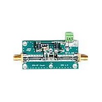
... Transmission line W = 0.92mm TL6 Transmission line W = 0.92mm in, RF out SMA-CONN PD84002 LDMOS Board Figure 8. Demoboard photo 8/16 Value Case size Manufacturer Ω 60 mils Johnson STMicroelectronics FR-4 THk=0.020" 2OZ Cu both sides Doc ID 18013 Rev 1 STEVAL-TDR013V1 Part code 142-0701-801 PD84002 ...
Page 9
... STEVAL-TDR013V1 6 Circuit layout Figure 9. Test fixture component layout Figure 10. Test circuit photomaster Doc ID 18013 Rev 1 Circuit layout 9/16 ...
Page 10
... Package mechanical data 7 Package mechanical data In order to meet environmental requirements, ST offers these devices in different grades of ® ECOPACK packages, depending on their level of environmental compliance. ECOPACK specifications, grade definitions and product status are available at: www.st.com. ECOPACK trademark. 10/16 Doc ID 18013 Rev 1 STEVAL-TDR013V1 ® ...
Page 11
... STEVAL-TDR013V1 Table 6. SOT-89 mechanical data Dim Figure 11. Package dimensions mm. Min Typ Max 1.4 1.6 0.44 0.56 0.36 0.48 0.35 0.44 0.35 0.44 4.4 4.6 1.62 1.83 2.29 2.6 1.42 1.57 2.92 3.07 3.94 4.25 0.89 1.2 Doc ID 18013 Rev 1 Package mechanical data ...
Page 12
... The via pattern is based on thru-hole vias with 0.203mm to 0.330mm finished hole size on a 0.5mm to 1.2mm grid pattern with 0.025 plating on via walls. If micro vias are used in a design suggested that the quantity of vias be increased by a 4:1 ratio to achieve similar results. Figure 12. Pad layout details 12/16 Doc ID 18013 Rev 1 STEVAL-TDR013V1 ...
Page 13
... STEVAL-TDR013V1 7.2 Soldering profile Figure 13 shows the recommeded solder for devices that have Pb-free terminal plating and where a Pb-free solder is used. Figure 13. Recommended solder profile Figure 14 shows the recommeded solder for devices with Pb-free terminal plating used with leaded solder, or for devices with leaded terminal plating used with a leaded solder. ...
Page 14
... Package mechanical data Figure 15. Reel information 14/16 Doc ID 18013 Rev 1 STEVAL-TDR013V1 ...
Page 15
... STEVAL-TDR013V1 8 Revision history Updated Table 7. Document revision history Date 22-Sep-2007 Revision 1 Initial release Doc ID 18013 Rev 1 Revision history Changes 15/16 ...
Page 16
... Australia - Belgium - Brazil - Canada - China - Czech Republic - Finland - France - Germany - Hong Kong - India - Israel - Italy - Japan - Malaysia - Malta - Morocco - Philippines - Singapore - Spain - Sweden - Switzerland - United Kingdom - United States of America 16/16 Please Read Carefully: © 2010 STMicroelectronics - All rights reserved STMicroelectronics group of companies www.st.com Doc ID 18013 Rev 1 STEVAL-TDR013V1 ...