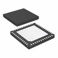
ATA5279P-PLQW Atmel, ATA5279P-PLQW Datasheet - Page 20

ATA5279P-PLQW
Manufacturer Part Number
ATA5279P-PLQW
Description
IC ANTENNA DVR SIX-FOLD 48QFN
Manufacturer
Atmel
Datasheet
1.ATA5279P-PLQW.pdf
(40 pages)
Specifications of ATA5279P-PLQW
Rf Type
PEG, TPMS
Frequency
125kHz
Features
RSSI Equipped
Package / Case
48-VQFN Exposed Pad, 48-HVQFN, 48-SQFN, 48-DHVQFN
Lead Free Status / RoHS Status
Lead free / RoHS Compliant
Available stocks
Company
Part Number
Manufacturer
Quantity
Price
Company:
Part Number:
ATA5279P-PLQW
Manufacturer:
ATMEL
Quantity:
3 500
Part Number:
ATA5279P-PLQW
Manufacturer:
ATMEL/爱特梅尔
Quantity:
20 000
In this example, the output signal of the modulator resembles the illustration below.
Figure 3-13. Example of Data Transmission of Two Consecutive Commands
First Command
Second Command
Modulator Data
BCNT Signal
2
t
24
t
data
data
26
t
data
The value for t
depends on the speed setting of the modulator (32LF periods in standard
data
and 22 periods in high speed mode, with one period being 8µs when operating with 125kHz
output frequency and therefore 8MHz system clock).
The least amount of data that can be processed by the modulator stage is four LF bits or two
(e.g. Manchester-encoded) data bits. The first command in the upper example is a mini-
mum-length LF data command.
To ensure the traceability of the LF protocol, two pins are provided, which indicate an active
data transmission (MACT) and the change of an LF bit (BCNT).
Figure 3-12
illustrates the
function of these two signals:
Figure 3-14. LF Transmission Tracing Signals
Modulator Data
off
1
0
1
1
0
1
1
off
Transmitter Coil Current
Current Envelope
MACT Signal
BCNT Signal
The MACT signal can be used to start a timer whereas BCNT can be used as input signal to a
counter. Note that for carrier transmissions, only the MACT signal is active. There are not any
pulses on the BCNT line.
Atmel ATA5279
20
9125L–RKE–03/11


