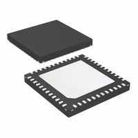
ATA5279P-PLPW Atmel, ATA5279P-PLPW Datasheet - Page 35

ATA5279P-PLPW
Manufacturer Part Number
ATA5279P-PLPW
Description
IC ANTENNA DVR SIX-FOLD 48VQFN
Manufacturer
Atmel
Datasheet
1.ATA5279P-PLQW.pdf
(40 pages)
Specifications of ATA5279P-PLPW
Rf Type
PEG, TPMS
Frequency
125kHz
Features
RSSI Equipped
Package / Case
48-VFQFN Exposed Pad
Lead Free Status / RoHS Status
Lead free / RoHS Compliant
8. Functional Parameters (Continued)
All parameters valid for 7.0V VS 16.5V and –40°C T
9125L–RKE–03/11
*) Type means: A = 100% tested, B = 100% correlation tested, C = Characterized on samples, D = Design parameter
Notes:
10.10 Current step 10 level
10.11 Current step 11 level
10.12 Current step 12 level
10.13 Current step 13 level
10.14 Current step 14 level
10.1
10.2
10.3
10.4
10.5
10.6
10.7
10.8
10.9
No.
6.7
7.1
7.2
8.1
9.1
9.2
9.3
9.6
10
7
8
9
1. In this column, pin group names are given. Please refer to
2. Operation of coils with higher impedance than the given value is possible but functional limitations might occur (inability to
Parameters
Short circuit detection
AxP or AxN to Vbatt
Zero Crossing Detector
Pos. slope detection
threshold
Polarity detection delay
Sample and Hold Stage
Sampled differential
voltage
Integrator Stage
Input offset voltage
Positive output linearity
Negative output
linearity
Upper output voltage
limit
References
Current step 1 level
Current step 2 level
Current step 3 level
Current step 4 level
Current step 5 level
Current step 6 level
Current step 7 level
Current step 8 level
Current step 9 level
more details.
reach to configured coil current). Coils with lower impedance should not be used as they might be detected as faulty.
Test Conditions
Voltage jump from
V
V
Sampling state
Current step 20
selected
V
V
V
Current step 20
selected
V
Current step 20
selected
I
V
Current step 20
selected
CINT
VSHS
VSHS
VSHS
VSHS
VSHS
VSHS
SHS
= 30µA
= 100mV
– 20mV to
+ 20mV
= 200 mV
= 1 V
= 1.1V
= 0.9V
pp
pp
pp
p
pp
a
105°C unless otherwise noted.
HRL
LRL
Pin
5
5
5
5
3
3
3
-
-
-
-
-
-
-
-
-
-
-
-
-
-
V
Symbol
V
V
V
V
V
V
Section 2. “Pin Configuration” on page 2
I
V
V
V
V
V
V
V
V
V
I
V
V
INT,NEG
INT,POS
CINT,max
t
t
ofs,Integ
REF,S10
REF,S11
REF,S12
REF,S13
REF,S14
OLdet
V
ZCdel
REF,S1
REF,S2
REF,S3
REF,S4
REF,S5
REF,S6
REF,S7
REF,S8
REF,S9
smpl,1
smpl,2
ZC
Min.
–2.5
3.15
49.5
–10
150
830
440
–20
145
192
245
294
343
392
441
490
539
588
637
686
97
8
Typ.
Atmel ATA5279
Max.
+2.5
3.45
54.5
100
+10
290
970
560
105
157
208
255
306
357
408
459
510
561
612
663
714
–8
20
in this document for
Unit
mV
mV
mV
mV
mV
mV
mV
mV
mV
mV
mV
mV
mV
mV
mV
mV
mV
mV
µA
µA
µs
ns
V
Type*
B
A
A
A
B
A
A
A
A
A
A
A
A
A
A
A
A
A
A
A
A
A
35


