T40HFL20S05 Vishay, T40HFL20S05 Datasheet - Page 2
T40HFL20S05
Manufacturer Part Number
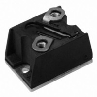
T40HFL20S05
Description
DIODE FAST REC 200V 40A D-56
Manufacturer
Vishay
Datasheet
1.T40HFL20S02.pdf
(15 pages)
Specifications of T40HFL20S05
Current - Reverse Leakage @ Vr
100µA @ 200V
Current - Average Rectified (io) (per Diode)
40A
Voltage - Dc Reverse (vr) (max)
200V
Reverse Recovery Time (trr)
500ns
Diode Type
Standard
Speed
Fast Recovery =< 500ns, > 200mA (Io)
Diode Configuration
Single
Mounting Type
Chassis Mount
Package / Case
D-55 T-Module
Product
Fast Recovery Rectifier
Configuration
Single
Reverse Voltage
200 V
Forward Voltage Drop
1.6 V
Recovery Time
500 ns
Forward Continuous Current
40 A
Max Surge Current
500 A
Reverse Current Ir
100 uA
Mounting Style
Screw
No. Of Phases
Single
Repetitive Reverse Voltage Vrrm Max
200V
Forward Current If(av)
40A
Forward Voltage Vf Max
1.6V
Module Configuration
Single
Peak Reflow Compatible (260 C)
Yes
Lead Free Status / RoHS Status
Lead free / RoHS Compliant
Voltage - Forward (vf) (max) @ If
-
Lead Free Status / RoHS Status
Lead free / RoHS Compliant, Lead free / RoHS Compliant
Other names
*T40HFL20S05
VS-T40HFL20S05
VS-T40HFL20S05
VST40HFL20S05
VST40HFL20S05
VS-T40HFL20S05
VS-T40HFL20S05
VST40HFL20S05
VST40HFL20S05


T40HFL, T70HFL, T85HFL Series
Vishay Semiconductors
ELECTRICAL SPECIFICATIONS
www.vishay.com
2
VOLTAGE RATINGS
TYPE NUMBER
T40HFL..
T70HFL..
T85HFL..
FORWARD CONDUCTION
PARAMETER
Maximum average
forward current
at case temperature
Maximum RMS
forward current
Maximum peak, one-cycle
forward, non-repetitive
surge current
Maximum I
Maximum I
Low level value of
threshold voltage
High level value of
threshold voltage
Low level value of forward
slope resistance
High level value of forward
slope resistance
Maximum forward
voltage drop
2
2
t for fusing
√t for fusing
VOLTAGE
CODE
100
10
20
40
60
80
DiodesAmericas@vishay.com, DiodesAsia@vishay.com,
For technical questions within your region, please contact one of the following:
SYMBOL
I
V
V
F(RMS)
I
I
S02, S05, S10
S02, S05, S10
S02, S05, S10
S02, S05, S10
V
I
F(TO)1
F(TO)2
F(AV)
FSM
I
2
r
r
2
FM
√t
f1
f2
t
S05, S10
S05, S10
CODE
t
rr
180° conduction, half sine wave
t = 10 ms
t = 8.3 ms
t = 10 ms
t = 8.3 ms
t = 10 ms
t = 8.3 ms
t = 10 ms
t = 8.3 ms
t = 0.1 ms to 10 ms, no voltage reapplied
T
T
T
T
I
Average power = V
FM
J
J
J
J
= 25 °C, (16.7 % x π x I
= 25 °C, (I > π x I
= 25 °C, (16.7 % x π x I
= 25 °C, (I > π x I
(T-Modules), 40 A/70 A/85 A
= π x I
Fast Recovery Diodes
V
F(AV)
RRM,
PEAK REVERSE VOLTAGE
No voltage
reapplied
100 % V
reapplied
No voltage
reapplied
100 % V
reapplied
, T
TEST CONDITIONS
MAXIMUM REPETITIVE
J
= 25 °C, t
F(TO)
F(AV)
F(AV)
RRM
RRM
1000
100
200
400
600
800
)
)
x I
V
F(AV)
F(AV)
F(AV)
p
Sinusoidal half wave,
initial T
= 400 μs square wave
< I < π x I
< I < π x I
+ r
f
x (I
J
= T
F(RMS)
DiodesEurope@vishay.com
F(AV)
F(AV)
J
maximum
)
2
)
)
NON-REPETITIVE PEAK
REVERSE VOLTAGE
V
RSM
T40HFL
, MAXIMUM
11 300
1100
1130
1030
0.82
0.84
1.60
475
500
400
420
800
730
150
300
500
700
900
7.0
6.8
40
63
V
T70HFL
34 600
3460
3160
2450
2230
0.87
0.90
2.77
2.67
1.73
110
830
870
700
730
70
70
Document Number: 93184
Revision: 19-May-10
I
T85HFL
RRM
85 500
AT T
1300
1370
1100
1150
8550
7810
6050
5520
0.84
0.86
2.15
2.07
1.55
133
85
MAXIMUM
J
100
μA
= 25 °C
UNITS
A
A
mΩ
°C
2
A
A
A
V
V
2
√s
s
Related parts for T40HFL20S05
Image
Part Number
Description
Manufacturer
Datasheet
Request
R

Part Number:
Description:
357-036-542-201 CARDEDGE 36POS DL .156 BLK LOPRO
Manufacturer:
Vishay
Datasheet:
Part Number:
Description:
357-036-542-201 CARDEDGE 36POS DL .156 BLK LOPRO
Manufacturer:
Vishay
Datasheet:
Part Number:
Description:
357-036-542-201 CARDEDGE 36POS DL .156 BLK LOPRO
Manufacturer:
Vishay
Datasheet:
Part Number:
Description:
357-036-542-201 CARDEDGE 36POS DL .156 BLK LOPRO
Manufacturer:
Vishay
Datasheet:
Part Number:
Description:
357-036-542-201 CARDEDGE 36POS DL .156 BLK LOPRO
Manufacturer:
Vishay
Datasheet:
Part Number:
Description:
357-036-542-201 CARDEDGE 36POS DL .156 BLK LOPRO
Manufacturer:
Vishay
Datasheet:
Part Number:
Description:
357-036-542-201 CARDEDGE 36POS DL .156 BLK LOPRO
Manufacturer:
Vishay
Datasheet:
Part Number:
Description:
357-036-542-201 CARDEDGE 36POS DL .156 BLK LOPRO
Manufacturer:
Vishay
Datasheet:
Part Number:
Description:
357-036-542-201 CARDEDGE 36POS DL .156 BLK LOPRO
Manufacturer:
Vishay
Datasheet:
Part Number:
Description:
357-036-542-201 CARDEDGE 36POS DL .156 BLK LOPRO
Manufacturer:
Vishay
Datasheet:
Part Number:
Description:
357-036-542-201 CARDEDGE 36POS DL .156 BLK LOPRO
Manufacturer:
Vishay
Datasheet:
Part Number:
Description:
357-036-542-201 CARDEDGE 36POS DL .156 BLK LOPRO
Manufacturer:
Vishay
Datasheet:
Part Number:
Description:
357-036-542-201 CARDEDGE 36POS DL .156 BLK LOPRO
Manufacturer:
Vishay
Datasheet:
Part Number:
Description:
357-036-542-201 CARDEDGE 36POS DL .156 BLK LOPRO
Manufacturer:
Vishay
Datasheet:
Part Number:
Description:
357-036-542-201 CARDEDGE 36POS DL .156 BLK LOPRO
Manufacturer:
Vishay
Datasheet: