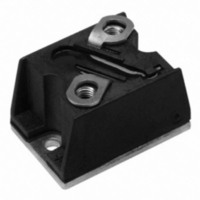
T40HFL60S02 Vishay, T40HFL60S02 Datasheet - Page 5
T40HFL60S02
Manufacturer Part Number
T40HFL60S02
Description
DIODE FAST REC 600V 40A D-55
Manufacturer
Vishay
Datasheet
1.T40HFL20S02.pdf
(15 pages)
Specifications of T40HFL60S02
Current - Reverse Leakage @ Vr
100µA @ 600V
Current - Average Rectified (io) (per Diode)
40A
Voltage - Dc Reverse (vr) (max)
600V
Reverse Recovery Time (trr)
200ns
Diode Type
Standard
Speed
Fast Recovery =< 500ns, > 200mA (Io)
Diode Configuration
Single
Mounting Type
Chassis Mount
Package / Case
D-55
Product
Fast Recovery Rectifier
Configuration
Single
Reverse Voltage
600 V
Forward Voltage Drop
1.6 V
Recovery Time
200 ns
Forward Continuous Current
40 A
Max Surge Current
500 A
Reverse Current Ir
100 uA
Mounting Style
Screw
Maximum Operating Temperature
+ 125 C
Minimum Operating Temperature
- 40 C
No. Of Phases
Single
Repetitive Reverse Voltage Vrrm Max
600V
Forward Current If(av)
40A
Forward Voltage Vf Max
1.6V
Module Configuration
Single
Peak Reflow Compatible (260 C)
Yes
Lead Free Status / RoHS Status
Lead free / RoHS Compliant
Voltage - Forward (vf) (max) @ If
-
Lead Free Status / RoHS Status
Lead free / RoHS Compliant, Lead free / RoHS Compliant
Other names
*T40HFL60S02


Document Number: 93184
Revision: 19-May-10
100
70
60
50
40
30
20
10
Fig. 7 - Forward Power Loss Characteristics
90
80
70
60
50
40
30
20
10
Fig. 8 - Forward Power Loss Characteristics
Fig. 9 - Forward Power Loss Characteristics
90
80
70
60
50
40
30
20
10
0
0
0
0
0
0
RMS Limit
180°
120°
DC
5
90°
60°
30°
10
10
Average F orward Current (A)
Average Forward Current (A)
Average F orward Current (A)
RMS Limit
180°
120°
10
90°
60°
30°
RMS Limit
20
20
180°
120°
90°
60°
30°
15
DiodesAmericas@vishay.com, DiodesAsia@vishay.com,
30
30
For technical questions within your region, please contact one of the following:
20
Conduc tion Period
40
Conduc tion Angle
40
Conduc tion Angle
T 40HF L.. S eries
T = 125°C
T 70HF L.. S eries
T = 125°C
T 40HF L.. S eries
T = 125°C
J
25
J
J
50
50
30
60
60
35
(T-Modules), 40 A/70 A/85 A
40
70
70
Fast Recovery Diodes
T40HFL, T70HFL, T85HFL Series
140
120
100
160
140
120
100
DiodesEurope@vishay.com
110
100
Fig. 10 - Forward Power Loss Characteristics
Fig. 11 - Forward Power Loss Characteristics
Fig. 12 - Forward Power Loss Characteristics
80
60
40
20
80
60
40
20
90
80
70
60
50
40
30
20
10
0
0
0
0
0
0
RMS Limit
RMS Limit
180°
120°
180°
120°
10 20 30 40 50 60 70 80 90
DC
90°
60°
30°
DC
90°
60°
30°
20
Average F orward Current (A)
Average F orward Current (A)
20
Average Forward Current (A)
180°
120°
RMS Limit
90°
60°
30°
40
Vishay Semiconductors
40
60
60
Conduc tion Period
Conduc tion Period
80
Conduc tion Angle
T 85HFL.. S eries
T = 125°C
T 70HF L.. S eries
T = 125°C
T 85HFL.. S eries
T = 125°C
J
J
J
80
100
100
120
140
www.vishay.com
120
5
Related parts for T40HFL60S02
Image
Part Number
Description
Manufacturer
Datasheet
Request
R

Part Number:
Description:
357-036-542-201 CARDEDGE 36POS DL .156 BLK LOPRO
Manufacturer:
Vishay
Datasheet:
Part Number:
Description:
357-036-542-201 CARDEDGE 36POS DL .156 BLK LOPRO
Manufacturer:
Vishay
Datasheet:
Part Number:
Description:
357-036-542-201 CARDEDGE 36POS DL .156 BLK LOPRO
Manufacturer:
Vishay
Datasheet:
Part Number:
Description:
357-036-542-201 CARDEDGE 36POS DL .156 BLK LOPRO
Manufacturer:
Vishay
Datasheet:
Part Number:
Description:
357-036-542-201 CARDEDGE 36POS DL .156 BLK LOPRO
Manufacturer:
Vishay
Datasheet:
Part Number:
Description:
357-036-542-201 CARDEDGE 36POS DL .156 BLK LOPRO
Manufacturer:
Vishay
Datasheet:
Part Number:
Description:
357-036-542-201 CARDEDGE 36POS DL .156 BLK LOPRO
Manufacturer:
Vishay
Datasheet:
Part Number:
Description:
357-036-542-201 CARDEDGE 36POS DL .156 BLK LOPRO
Manufacturer:
Vishay
Datasheet:
Part Number:
Description:
357-036-542-201 CARDEDGE 36POS DL .156 BLK LOPRO
Manufacturer:
Vishay
Datasheet:
Part Number:
Description:
357-036-542-201 CARDEDGE 36POS DL .156 BLK LOPRO
Manufacturer:
Vishay
Datasheet:
Part Number:
Description:
357-036-542-201 CARDEDGE 36POS DL .156 BLK LOPRO
Manufacturer:
Vishay
Datasheet:
Part Number:
Description:
357-036-542-201 CARDEDGE 36POS DL .156 BLK LOPRO
Manufacturer:
Vishay
Datasheet:
Part Number:
Description:
357-036-542-201 CARDEDGE 36POS DL .156 BLK LOPRO
Manufacturer:
Vishay
Datasheet:
Part Number:
Description:
357-036-542-201 CARDEDGE 36POS DL .156 BLK LOPRO
Manufacturer:
Vishay
Datasheet:
Part Number:
Description:
357-036-542-201 CARDEDGE 36POS DL .156 BLK LOPRO
Manufacturer:
Vishay
Datasheet: