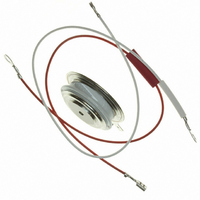
SD400C08C Vishay, SD400C08C Datasheet - Page 5

SD400C08C
Manufacturer Part Number
SD400C08C
Description
DIODE STD REC 800V 800A A-PUK
Manufacturer
Vishay
Specifications of SD400C08C
Diode Type
Standard
Voltage - Forward (vf) (max) @ If
1.86V @ 1930A
Current - Reverse Leakage @ Vr
15mA @ 800V
Current - Average Rectified (io) (per Diode)
800A
Voltage - Dc Reverse (vr) (max)
800V
Speed
Standard Recovery >500ns, > 200mA (Io)
Diode Configuration
Single
Mounting Type
Chassis Mount
Package / Case
DO-200AA, A-PUK
Product
Standard Recovery Rectifier
Configuration
Single
Reverse Voltage
800 V
Forward Voltage Drop
1.86 V at 1930 A
Forward Continuous Current
800 A
Max Surge Current
8640 A
Reverse Current Ir
15000 uA
Mounting Style
SMD/SMT
Maximum Operating Temperature
+ 190 C
Minimum Operating Temperature
- 40 C
Repetitive Reverse Voltage Vrrm Max
800V
Forward Current If(av)
800A
Forward Voltage Vf Max
1.86V
Forward Surge Current Ifsm Max
7.265kA
Diode Case Style
DO-200AA
Lead Free Status / RoHS Status
Lead free / RoHS Compliant
Reverse Recovery Time (trr)
-
Lead Free Status / RoHS Status
Lead free / RoHS Compliant, Lead free / RoHS Compliant
Other names
*SD400C08C
VS-SD400C08C
VS-SD400C08C
VSSD400C08C
VSSD400C08C
VS-SD400C08C
VS-SD400C08C
VSSD400C08C
VSSD400C08C
Document Number: 93547
Num b er O f E q ua l A m p litud e H a lf Cy cle C urrent P u lses (N )
2 0 0 0
1 8 0 0
1 6 0 0
1 4 0 0
1 2 0 0
1 0 0 0
8 00 0
7 00 0
6 00 0
5 00 0
4 00 0
3 00 0
2 00 0
2 0 0
1 8 0
1 6 0
1 4 0
1 2 0
1 0 0
8 0 0
6 0 0
4 0 0
2 0 0
80
60
40
20
0
0
Fig. 7 - Maximum Non-Repetitive Surge Current
0
0
1
Fig. 5 - Forward Power Loss Characteristics
A t An y Rated Loa d C on d itio n A nd W ith
SD 400C ..C Se ries
Fig. 3 - Current Ratings Characteristics
Ra ted V
180
120
Avera ge Forw a rd C urrent (A )
A vera ge Forw a rd C urren t (A )
2 0 0
2 0 0
Single and Double Side Cooled
90
60
30
30
R R M
SD 400C ..C Series
(D oub le Sid e C ooled )
R
4 00
4 00
thJ-h s
Ap p lied Follow in g Surg e.
60
10
(D C ) = 0.073 K/W
SD 400C ..C Series
T = 190 C
60 0
6 0 0
90
C o nd uctio n A n gle
J
C o nd u ction A ng le
Initia l T = 190 C
@ 60 H z 0.0083 s
@ 50 H z 0.0100 s
120
RM S Lim it
J
8 0 0
8 0 0
180
1 0 0 0
1 0 0 0
10 0
9 000
8 000
7 000
6 000
5 000
4 000
3 000
2 000
2 5 0 0
2 0 0 0
1 5 0 0
1 0 0 0
50 0
20 0
18 0
16 0
14 0
12 0
10 0
80
60
40
20
0
0
0 .01
Fig. 8 - Maximum Non-Repetitive Surge Current
0
0
Fig. 6 - Forward Power Loss Characteristics
M axim um Non Repetitive Surge C urren t
180
120
SD 400C ..C Series
D C
Fig. 4 - Current Ratings Characteristics
90
60
30
30
Avera g e Forw ard C urren t (A )
A vera ge Forw a rd C urren t (A )
Single and Double Side Cooled
4 00
Pulse Train D uration (s)
40 0
60
Bulletin I2084 rev. D 11/01
90
V ersus Pulse Train D ura tion .
SD 400C ..C Series
(D ouble Side C ooled)
R
SD400C..C Series
th J-hs
120
Ra te d V
No V olta g e Rea pp lied
80 0
8 00
0.1
(D C ) = 0.073 K/W
C o nd uctio n P erio d
C o nd uction P erio d
180
SD 400C ..C Series
T = 190 C
J
www.vishay.com
In itia l T = 190 C
RRM
1 20 0
1 2 00
Rea pp lied
RM S Lim it
D C
J
1 6 00
1 6 0 0
1
5


