VSKJ320-16 Vishay, VSKJ320-16 Datasheet - Page 3
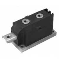
VSKJ320-16
Manufacturer Part Number
VSKJ320-16
Description
DIODE STD REC 1600V 320A MAGNAPK
Manufacturer
Vishay
Datasheet
1.VSKE320-04.pdf
(12 pages)
Specifications of VSKJ320-16
Current - Reverse Leakage @ Vr
50mA @ 1600V
Current - Average Rectified (io) (per Diode)
320A
Voltage - Dc Reverse (vr) (max)
1600V (1.6kV)
Diode Type
Standard
Speed
Standard Recovery >500ns, > 200mA (Io)
Diode Configuration
1 Pair Common Anode
Mounting Type
Chassis Mount
Package / Case
3-MAGN-A-PAK™
Product
Standard Recovery Rectifier
Configuration
Dual Common Anode
Reverse Voltage
1600 V
Forward Voltage Drop
1.28 V
Forward Continuous Current
320 A
Max Surge Current
10580 A
Reverse Current Ir
50000 uA
Mounting Style
Screw
Maximum Operating Temperature
+ 150 C
Minimum Operating Temperature
- 40 C
Lead Free Status / RoHS Status
Lead free / RoHS Compliant
Reverse Recovery Time (trr)
-
Voltage - Forward (vf) (max) @ If
-
Lead Free Status / RoHS Status
Lead free / RoHS Compliant, Lead free / RoHS Compliant
Other names
*IRKJ320-16
IRKJ320-16
IRKJ320-16
IRKJ320-16
IRKJ320-16


Note
• The table above shows the increment of thermal resistance R
Document Number: 93581
Revision: 02-Jul-10
THERMAL AND MECHANICAL SPECIFICATIONS
PARAMETER
Maximum junction operating and storage
temperature range
Maximum thermal resistance,
junction to case per junction
Maximum resistance, case to heatsink
per module
Mounting torque
± 10 %
Approximate weight
Case style
R CONDUCTION PER JUNCTION
DEVICE
VSK.250
VSK.270
VSK.320
0.009
0.008
0.008
180°
MAP to heatsink
busbar to MAP
DiodesAmericas@vishay.com, DiodesAsia@vishay.com,
For technical questions within your region, please contact one of the following:
SINUSOIDAL CONDUCTION
Standard Recovery Diodes, 250 A to 320 A
0.010
0.012
0.010
120°
AT T
(MAGN-A-PAK Power Modules)
J
0.014
0.014
0.013
MAXIMUM
90°
SYMBOL
T
R
R
J
, T
thJC
thCS
Stg
0.020
0.020
0.020
60°
DC operation
Mounting surface flat, smooth and
greased
A mounting compound is recommended
and the torque should be rechecked
after a period of about 3 hours to allow for
the spread of the compound.
0.032
0.032
0.032
thJC
30°
TEST CONDITIONS
when devices operate at different conduction angles than DC
VSK.250, VSK.270, VSK.320 Series
0.007
0.007
0.007
180°
RECTANGULAR CONDUCTION
0.011
0.011
0.011
120°
DiodesEurope@vishay.com
AT T
J
0.015
0.015
0.015
MAXIMUM
90°
Vishay Semiconductors
VSK.250 VSK.270 VSK.320
0.16
0.021
0.020
0.020
60°
- 40 to 150
VALUES
8 to 10
4 to 6
MAGN-A-PAK
0.035
800
0.033
0.033
0.033
30
30°
0.125
www.vishay.com
UNITS
K/W
UNITS
K/W
Nm
oz.
°C
g
3
Related parts for VSKJ320-16
Image
Part Number
Description
Manufacturer
Datasheet
Request
R

Part Number:
Description:
DIODE STD REC 800V 320A MAGNAPAK
Manufacturer:
Vishay
Datasheet:
Part Number:
Description:
DIODE STD REC 400V 320A MAGNAPAK
Manufacturer:
Vishay
Datasheet:
Part Number:
Description:
DIODE STD REC 1200V 320A MAGNAPK
Manufacturer:
Vishay
Datasheet:
Part Number:
Description:
DIODE STD REC 2000V 320A MAGNAPK
Manufacturer:
Vishay
Datasheet:

Part Number:
Description:
357-036-542-201 CARDEDGE 36POS DL .156 BLK LOPRO
Manufacturer:
Vishay
Datasheet:
Part Number:
Description:
357-036-542-201 CARDEDGE 36POS DL .156 BLK LOPRO
Manufacturer:
Vishay
Datasheet:
Part Number:
Description:
357-036-542-201 CARDEDGE 36POS DL .156 BLK LOPRO
Manufacturer:
Vishay
Datasheet:
Part Number:
Description:
357-036-542-201 CARDEDGE 36POS DL .156 BLK LOPRO
Manufacturer:
Vishay
Datasheet:
Part Number:
Description:
357-036-542-201 CARDEDGE 36POS DL .156 BLK LOPRO
Manufacturer:
Vishay
Datasheet:
Part Number:
Description:
357-036-542-201 CARDEDGE 36POS DL .156 BLK LOPRO
Manufacturer:
Vishay
Datasheet:
Part Number:
Description:
357-036-542-201 CARDEDGE 36POS DL .156 BLK LOPRO
Manufacturer:
Vishay
Datasheet:
Part Number:
Description:
357-036-542-201 CARDEDGE 36POS DL .156 BLK LOPRO
Manufacturer:
Vishay
Datasheet:
Part Number:
Description:
357-036-542-201 CARDEDGE 36POS DL .156 BLK LOPRO
Manufacturer:
Vishay
Datasheet:
Part Number:
Description:
357-036-542-201 CARDEDGE 36POS DL .156 BLK LOPRO
Manufacturer:
Vishay
Datasheet:
Part Number:
Description:
357-036-542-201 CARDEDGE 36POS DL .156 BLK LOPRO
Manufacturer:
Vishay
Datasheet: