CM450DX-24S Powerex Inc, CM450DX-24S Datasheet - Page 5
CM450DX-24S
Manufacturer Part Number
CM450DX-24S
Description
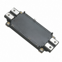
IGBT MOD DUAL 1200V 450A NX SER
Manufacturer
Powerex Inc
Series
IGBTMOD™r
Type
Dualr
Datasheet
1.CM450DX-24S.pdf
(6 pages)
Specifications of CM450DX-24S
Featured Product
6th Generation NX-S Series IGBTs
Configuration
Half Bridge
Voltage - Collector Emitter Breakdown (max)
1200V
Vce(on) (max) @ Vge, Ic
2.15V @ 15V, 450A
Current - Collector (ic) (max)
450A
Current - Collector Cutoff (max)
1mA
Input Capacitance (cies) @ Vce
45nF @ 10V
Power - Max
3400W
Input
Standard
Ntc Thermistor
Yes
Mounting Type
Chassis Mount
Package / Case
Module
Module Configuration
Dual
Dc Collector Current
450A
Collector Emitter Voltage Vces
1.2kV
Power Dissipation Pd
3.4W
Operating Temperature Range
-40°C To +150°C
Peak Reflow Compatible (260 C)
Yes
Rohs Compliant
Yes
Leaded Process Compatible
Yes
Prx Availability
RequestQuote
Distributorinventory
View
Voltage
1200V
Current
450A
Circuit Configuration
Dual
Recommended Gate Driver
VLA503-01
Recommended Dc To Dc Converter
VLA106-15242
Interface Circuit Ref Design
VLA536-01R
Lead Free Status / RoHS Status
Lead free / RoHS Compliant
Igbt Type
-
Lead Free Status / RoHS Status
Lead free / RoHS Compliant
Other names
835-1125
Available stocks
Company
Part Number
Manufacturer
Quantity
Price
Company:

Part Number:
CM450DX-24S
Manufacturer:
artesyn
Quantity:
1 000
Part Number:
CM450DX-24S
Manufacturer:
MIT
Quantity:
20 000


Powerex, Inc., 173 Pavilion Lane, Youngwood, Pennsylvania 15697 (724) 925-7272 www.pwrx.com
CM450DX-24S
Dual IGBTMOD™ NX-S Series Module
450 Amperes/1200 Volts
04/10 Rev. 0
900
800
700
600
500
400
300
200
100
10
10
10
10
10
10
10
0
3
2
1
0
3
2
1
10
0
0
-1
COLLECTOR-EMITTER VOLTAGE, V
EMITTER-COLLECTOR VOLTAGE, V
V
GE
20V
FORWARD CHARACTERISTICS
0.5
=
OUTPUT CHARACTERISTICS
(INVERTER PART - TYPICAL)
(INVERTER PART - TYPICAL)
(INVERTER PART - TYPICAL)
2
GATE RESISTANCE, R
SWITCHING TIME VS.
FREE-WHEEL DIODE
GATE RESISTANCE
1.0
10
15
13.5
0
4
1.5
t
t
f
t
d(on)
r
6
V
t
2.0
d(off)
GE
10
V
V
I
T
Inductive Load
C
G
CC
GE
j
, (Ω)
= 150°C
1
= 15V
= 450A
T
T
T
CE
EC
j
j
j
= 600V
= ±15V
T
= 25°C
= 125°C
= 150°C
, (VOLTS)
, (VOLTS)
8
2.5
j
12
10
= 25° C
11
9
10
3.0
10
2
10
10
10
10
10
10
10
10
3.5
3.0
2.5
2.0
1.5
1.0
0.5
-1
-2
0
2
1
0
3
2
1
10
10
SATURATION VOLTAGE CHARACTERISTICS
0
REVERSE RECOVERY CHARACTERISTICS
-1
1
COLLECTOR-EMITTER VOLTAGE, V
V
100 200 300
GE
COLLECTOR-CURRENT, I
EMITTER CURRENT, I
(INVERTER PART - TYPICAL)
(INVERTER PART - TYPICAL)
= 15V
(INVERTER PART - TYPICAL)
T
T
T
j
j
j
CAPACITANCE VS. V CE
COLLECTOR-EMITTER
= 25°C
= 125°C
= 150°C
10
0
400
10
500 600
2
E
, (AMPERES)
C
10
, (AMPERES)
V
V
R
T
Inductive Load
CC
GE
j
G
1
= 150°C
C
C
C
700
= 1.6W
CE
oes
res
ies
= 600V
= ±15V
V
I
t
, (VOLTS)
rr
rr
GE
800
= 0V
900
10
10
2
3
10
10
10
20
16
12
10
8
4
0
8
6
4
2
0
3
2
1
10
SATURATION VOLTAGE CHARACTERISTICS
0
6
1
I
V
C
CC
GATE-EMITTER VOLTAGE, V
COLLECTOR CURRENT, I
SWITCHING CHARACTERISTICS
= 450A
250
8
(INVERTER PART - TYPICAL)
(INVERTER PART - TYPICAL)
= 600V
t
t
GATE CHARGE VS. V GE
d(off)
d(on)
COLLECTOR-EMITTER
10
GATE CHARGE, Q
(INVERTER PART)
t
500
r
HALF-BRIDGE
12
750 1000 1250 1500
10
I
2
C
14
I
C
= 900A
= 450A
G
C
I
C
, (nC)
, (AMPERES)
V
V
R
T
Inductive Load
GE
j
= 180A
CC
GE
G
16
= 150°C
, (VOLTS)
= 1.6W
T
= 600V
= ±15V
j
= 25°C
18
t
f
10
20
3
5
Related parts for CM450DX-24S
Image
Part Number
Description
Manufacturer
Datasheet
Request
R

Part Number:
Description:
IGBT MOD DUAL 1200V 450A NX SER
Manufacturer:
Powerex Inc
Datasheet:

Part Number:
Description:
Lamps DISC BY CML 2/99
Manufacturer:
CHICAGO MINIATURE LIGHTING, LLC
Datasheet:

Part Number:
Description:
NPN SILICON RF POWER TRANSISTOR
Manufacturer:
Advanced Semiconductor, Inc.

Part Number:
Description:
INDUCTOR CHIP SMD
Manufacturer:
Bourns Inc.
Datasheet:
Part Number:
Description:
INDUCTOR CHIP SMD
Manufacturer:
Bourns Inc.
Datasheet:

Part Number:
Description:
INDUCTOR CHIP SMD
Manufacturer:
Bourns Inc.
Datasheet:
Part Number:
Description:
INDUCTOR CHIP SMD
Manufacturer:
Bourns Inc.
Datasheet:
Part Number:
Description:
INDUCTOR CHIP SMD
Manufacturer:
Bourns Inc.
Datasheet:

Part Number:
Description:
INDUCTOR CHIP SMD
Manufacturer:
Bourns Inc.
Datasheet:
Part Number:
Description:
INDUCTOR CHIP SMD
Manufacturer:
Bourns Inc.
Datasheet:

Part Number:
Description:
Manufacturer:
Powerex Inc
Datasheet:
Part Number:
Description:
Manufacturer:
Powerex Inc
Datasheet:
Part Number:
Description:
Manufacturer:
Powerex Inc
Datasheet:
Part Number:
Description:
Manufacturer:
Powerex Inc
Datasheet:
Part Number:
Description:
Manufacturer:
Powerex Inc
Datasheet: