IXSN80N60AU1 IXYS, IXSN80N60AU1 Datasheet

IGBT 100A 600V SOT-227B

IXSN80N60AU1

Manufacturer Part Number
IXSN80N60AU1
Description
IGBT 100A 600V SOT-227B
Manufacturer
IXYS
Datasheet

Specifications of IXSN80N60AU1

Configuration
Single
Voltage - Collector Emitter Breakdown (max)
600V
Vce(on) (max) @ Vge, Ic
3V @ 15V, 80A
Current - Collector (ic) (max)
160A
Current - Collector Cutoff (max)
1mA
Input Capacitance (cies) @ Vce
8.5nF @ 25V
Power - Max
500W
Input
Standard
Ntc Thermistor
No
Mounting Type
Chassis Mount
Package / Case
SOT-227, miniBLOC
Channel Type
N
Collector-emitter Voltage
600V
Gate To Emitter Voltage (max)
±20V
Mounting
Screw
Operating Temperature (max)
150C
Operating Temperature Classification
Military
Lead Free Status / RoHS Status
Lead free / RoHS Compliant
Igbt Type
-
Lead Free Status / RoHS Status
Compliant, Lead free / RoHS Compliant
© 2000 IXYS All rights reserved
IGBT with Diode
Short Circuit SOA Capability
Symbol
V
V
V
V
I
I
I
SSOA
(RBSOA)
t
(SCSOA)
P
V
T
T
T
M
Weight
Symbol
BV
V
I
I
V
IXYS reserves the right to change limits, test conditions, and dimensions.
C25
C90
CM
CES
GES
SC
J
JM
stg
CGR
C
CES
GES
GEM
ISOL
GE(th)
CE(sat)
d
CES
Test Conditions
T
T
Continuous
Transient
T
T
T
V
Clamped inductive load, L = 30 mH
V
R
T
50/60 Hz
I
Mounting torque
Terminal connection torque (M4)
Test Conditions
I
I
V
V
V
I
C
C
C
ISOL
C
C
C
C
J
J
GE
GE
CE
GE
CE
G
= 22 W, non repetitive
= 25°C to 150°C
= 25°C to 150°C; R
= 25°C
= 90°C
= 25°C, 1 ms
= 15 V, T
= 15 V, V
= 25°C
£ 1 mA
= 3 mA, V
= 8 mA, V
= 0.8 • V
= 0 V
= 0 V, V
= I
C90
, V
GE
GE
VJ
CE
CES
GE
CE
= 125°C, R
= 15 V
= 360 V, T
= ±20 V
= V
= 0 V
GE
t = 1 min
t = 1 s
GE
= 1 MW
J
G
= 125°C
= 22 W
T
T
J
J
(T
= 25°C
= 125°C
J
= 25°C, unless otherwise specified)
IXSN 80N60AU1
min.
600
Characteristic Values
4
-55 ... +150
-55 ... +150
@ 0.8 V
Maximum Ratings
I
CM
typ.
1.5/13 Nm/lb.in.
1.5/13 Nm/lb.in.
= 160
2500
3000
600
600
±20
±30
160
320
500
150
CES
10
80
30
G
E
max.
±100
15
8
1
3
C
mA
mA
E
V~
V~
°C
°C
°C
ms
ns
W
V
A
V
V
A
A
A
A
V
V
V
g
miniBLOC, SOT-227 B
E = Emitter ,
G = Gate,
 Either Emitter terminal can be used as
Main or Kelvin Emitter
Features
l
l
l
l
l
l
l
l
Applications
l
l
l
l
l
Advantages
l
l
l
V
I
V
C25
International standard package
miniBLOC
Aluminium-nitride isolation
- high power dissipation
Isolation voltage 3000 V~
UL registered E 153432
Low V
- for minimum on-state conduction
Fast Recovery Epitaxial Diode
- short t
Low collector-to-case capacitance
(< 60 pF)
- reduced RFI
Low package inductance (< 10 nH)
- easy to drive and to protect
Space savings
AC motor speed control
DC servo and robot drives
DC choppers
Uninterruptible power supplies (UPS)
Switch-mode and resonant-mode
power supplies
Easy to mount with 2 screws
High power density
CES
CE(sat)
losses
E153432
CE(sat)
rr
and I
= 600 V
= 160 A
=
C = Collector
E = Emitter 
RM
G
3 V
E
94552E(7/00)
C
1 - 4
E

Related parts for IXSN80N60AU1

IXSN80N60AU1 Summary of contents

Page 1

... V CES CE CES ± GES CE(sat) C C90 GE IXYS reserves the right to change limits, test conditions, and dimensions. © 2000 IXYS All rights reserved IXSN 80N60AU1 G E Maximum Ratings 600 = 1 MW 600 GE ±20 ±30 160 80 320 = 160 0.8 V CES = 125°C ...

Page 2

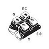
... J min. typ. max. /dt = 480 A/ 125°C 175 25° IXYS MOSFETS and IGBTs are covered by one or more of the following U.S. patents: 4,835,592 4,881,106 5,017,508 4,850,072 4,931,844 5,034,796 IXSN80N60AU1 miniBLOC, SOT-227 screws (4x) supplied nC Dim. Millimeter Min. Max 31.50 31.88 B 7.80 8. 4.09 4. ...

Page 3

... 125° Volts GE © 2000 IXYS All rights reserved 13V 11V 25° 160A 40° IXSN80N60AU1 Fig.2 Output Characterstics 400 T = 360 320 280 240 200 160 120 Volts CE Fig.4 Temperature Dependence of Output Saturation Voltage 1 160A V = 15V C GE 1.4 1.3 1.2 1.1 I ...

Page 4

... IXYS All rights reserved 24 1000 18 E off 100 120 140 160 1000 0.01 400 500 Diode IGBT 0.001 0.01 Time - Seconds IXSN80N60AU1 Fig.8 Dependence of Turn-Off Energy Per Pulse and Fall Time 125° 80A C 800 E off 600 400 t fi 200 ...

Related keywords