VWI15-12P1 IXYS, VWI15-12P1 Datasheet
VWI15-12P1
Manufacturer Part Number
VWI15-12P1
Description
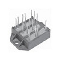
MODULE IGBT 18A 1200V ECO-PAC2
Manufacturer
IXYS
Datasheet
1.VWI15-12P1.pdf
(2 pages)
Specifications of VWI15-12P1
Igbt Type
NPT
Configuration
Three Phase Inverter
Voltage - Collector Emitter Breakdown (max)
1200V
Vce(on) (max) @ Vge, Ic
2.7V @ 15V, 10A
Current - Collector (ic) (max)
18A
Current - Collector Cutoff (max)
500µA
Input Capacitance (cies) @ Vce
0.6nF @ 25V
Power - Max
90W
Input
Standard
Ntc Thermistor
Yes
Mounting Type
Chassis Mount
Package / Case
ECO-PAC2
Channel Type
N
Collector-emitter Voltage
1.2kV
Collector Current (dc) (max)
18A
Gate To Emitter Voltage (max)
±20V
Pin Count
18
Mounting
Screw
Operating Temperature (min)
-40C
Operating Temperature (max)
150C
Operating Temperature Classification
Automotive
Lead Free Status / RoHS Status
Lead free / RoHS Compliant


IGBT Module
Sixpack in ECO-PAC 2
Preliminary data
Symbol
V
V
I
I
I
V
t
(SCSOA)
P
Symbol
V
V
I
I
t
t
t
t
E
E
C
Q
R
R
© 2003 IXYS All rights reserved
IXYS Semiconductor GmbH
Edisonstr. 15,
Phone: +49-6206-503-0, Fax: +49-6206-503627
IGBTs
C25
C80
CM
CES
GES
d(off)
IXYS reserves the right to change limits, test conditions and dimensions.
SC
d(on)
f
r
CES
GES
CEK
tot
CE(sat)
GE(th)
on
off
Gon
thJC
thJH
ies
Conditions
T
T
T
V
RBSOA, Clamped inductive load; L = 100 µH
V
non-repetitive
T
Conditions
I
I
V
V
V
V
(per IGBT)
(per IGBT) with heatsink compound
C
C
VJ
C
C
C
GE
CE
CE
CE
CE
CE
= 10 A; V
= 0.4 mA; V
D-68623 Lampertheim
= 25°C
= 80°C
= 25°C
Inductive load, T
V
V
= 25°C to 150°C
= 720 V; V
= V
= 600 V; V
= 0 V; V
= 25 V; V
= ±15 V; R
CE
GE
CES
= 600 V; I
= ±15 V; R
;
GE
GE
GE
GE
= 15 V; T
GE
GE
=
G
V
= 0 V; f = 1 MHz
= V
= 82
GE
= 15 V; I
= ±15 V; R
C
G
20 V
= 10 A
= 0 V; T
CE
= 82
VJ
T
= 125°C
VJ
; T
VJ
= 25°C
C
T
= 125°C
VJ
= 10 A
VJ
VJ
G
= 125°C
= 125°C
= 25°C
= 82
(T
N 5
G 1
S 9
A 1
F 3
L 9
VJ
= 25 C, unless otherwise specified)
; T
VJ
= 125°C
www.ixys.net
N 9
R 5
C 1
VWI 15-12P1
min.
4.5
Characteristic Values
Maximum Ratings
W 14
290
600
X 18
K 10
typ.
2.3
2.7
0.8
1.2
1.1
2.7
50
40
60
45
1200
V
18
14
CES
10
90
20
20
max.
200
2.7
6.5
0.5 mA
1.4 K/W
K/W
A 5
D 5
H 5
NTC
mA
µs
K 12
K 13
mJ
mJ
nC
W
nA
pF
ns
ns
ns
ns
V
V
A
A
A
V
V
V
IXYS Corporation
3540 Bassett Street, Santa Clara CA 95054
Phone: (408) 982-0700, Fax: 408-496-0670
I
V
V
Features
• NPT IGBT's
• FRED diodes
• Industry Standard Package
Typical Applications
• AC drives
• power supplies with power factor
C25
- positive temperature coefficient of
- fast switching
- fast reverse recovery
- low forward voltage
- solderable pins for PCB mounting
- isolated DCB ceramic base plate
correction
CES
CE(sat) typ.
saturation voltage
= 18 A
= 1200 V
= 2.3 V
Pin arangement see outlines
1 - 2
Related parts for VWI15-12P1
Image
Part Number
Description
Manufacturer
Datasheet
Request
R


Part Number:
Description:
HiPerFET Power MOSFETs
Manufacturer:
IXYS Corporation
Datasheet:
Part Number:
Description:
J-K-Type Flip-Flop
Manufacturer:
IXYS Corporation
Datasheet:
Part Number:
Description:
HiPerRF Power MOSFETs
Manufacturer:
IXYS Corporation
Datasheet:
Part Number:
Description:
Rectifier Module for Three Phase Power Factor Correction
Manufacturer:
IXYS Corporation
Datasheet:
Part Number:
Description:
Thyristor Modules Thyristor/Diode Modules
Manufacturer:
IXYS Corporation
Datasheet:
Part Number:
Description:
Thyristor Modules Thyristor/Diode Modules
Manufacturer:
IXYS Corporation
Datasheet:
Part Number:
Description:
Thyristor Modules Thyristor/Diode Modules
Manufacturer:
IXYS Corporation
Datasheet:
Part Number:
Description:
Thyristor Modules Thyristor/Diode Modules
Manufacturer:
IXYS Corporation
Datasheet:
Part Number:
Description:
Thyristor Modules /Diode Modules
Manufacturer:
IXYS Corporation
Datasheet:
Part Number:
Description:
Thyristor Modules /Diode Modules
Manufacturer:
IXYS Corporation
Datasheet:
Part Number:
Description:
Thyristor Modules Thyristor/Diode Modules
Manufacturer:
IXYS Corporation
Datasheet:
VWI15-12P1 Summary of contents
Page 1
... MHz ies 600 Gon (per IGBT) thJC R (per IGBT) with heatsink compound thJH IXYS reserves the right to change limits, test conditions and dimensions. © 2003 IXYS All rights reserved IXYS Semiconductor GmbH Edisonstr. 15, D-68623 Lampertheim Phone: +49-6206-503-0, Fax: +49-6206-503627 VWI 15-12P1 ...
Page 2
... Max. allowable acceleration Symbol Conditions d Creepage distance on surface S d Strike distance in air (Pin to heatsink) A Weight IXYS reserves the right to change limits, test conditions and dimensions. © 2003 IXYS All rights reserved Maximum Ratings 15 10 Characteristic Values min. typ. max. 2.6 3.0 1.9 = 125° ...