CM100TU-12F Powerex Inc, CM100TU-12F Datasheet - Page 2
CM100TU-12F
Manufacturer Part Number
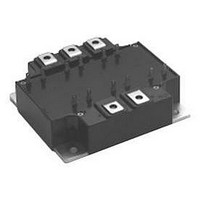
CM100TU-12F
Description
IGBT MOD 6PAC 600V 100A F SER
Manufacturer
Powerex Inc
Series
IGBTMOD™r
Datasheet
1.CM100TU-12F.pdf
(4 pages)
Specifications of CM100TU-12F
Configuration
Three Phase Inverter
Voltage - Collector Emitter Breakdown (max)
600V
Vce(on) (max) @ Vge, Ic
2.2V @ 15V, 100A
Current - Collector (ic) (max)
100A
Current - Collector Cutoff (max)
1mA
Input Capacitance (cies) @ Vce
27nF @ 10V
Power - Max
350W
Input
Standard
Ntc Thermistor
No
Mounting Type
Chassis Mount
Package / Case
Module
Collector Emitter Voltage Vces
600V
Continuous Collector Current Ic
100A
Collector Emitter Saturation Voltage Vce(sat)
1.6V
Current Rating
100A
Leaded Process Compatible
Yes
Voltage Rating
600V
Lead Free Status / RoHS Status
Lead free / RoHS Compliant
Igbt Type
-
Lead Free Status / RoHS Status
Lead free / RoHS Compliant, Lead free / RoHS Compliant
Available stocks
Company
Part Number
Manufacturer
Quantity
Price
Company:

Part Number:
CM100TU-12F
Manufacturer:
MITSUBISHI
Quantity:
26
Part Number:
CM100TU-12F
Manufacturer:
MITSUBISHI/三菱
Quantity:
20 000
Part Number:
CM100TU-12F
Quantity:
55


2
2
Powerex, Inc., 200 Hillis Street, Youngwood, Pennsylvania 15697-1800 (724) 925-7272
CM100TU-12F
Trench Gate Design Six IGBTMOD™
100 Amperes/600 Volts
Absolute Maximum Ratings, T
Ratings
Junction Temperature
Storage Temperature
Collector-Emitter Voltage (G-E SHORT)
Gate-Emitter Voltage (C-E SHORT)
Collector Current (T
Peak Collector Current (T
Emitter Current**
Peak Emitter Current**
Maximum Collector Dissipation (T
Mounting Torque, M4 Main Terminal
Mounting Torque, M5 Mounting
Weight
Isolation Voltage (Main Terminal to Baseplate, AC 1 min.)
Static Electrical Characteristics, T
Characteristics
Collector-Cutoff Current
Gate Leakage Current
Gate-Emitter Threshold Voltage
Collector-Emitter Saturation Voltage
Total Gate Charge
Emitter-Collector Voltage**
* Pulse width and repetition rate should be such that the device junction temperature (T
** Represents characteristics of the anti-parallel, emitter-to-collector free-wheel diode (FWDi).
c
= 25 C)
j
150 C)
j
< 150 C)
j
= 25 C unless otherwise specified
j
V
= 25 C unless otherwise specified
V
Symbol
I
CE(sat)
I
GE(th)
V
CES
GES
Q
EC
G
V
I
I
C
CC
C
= 100A, V
= 100A, V
= 300V, I
V
V
I
C
I
CE
GE
E
= 10mA, V
= 100A, V
= V
= V
Test Conditions
GE
C
GE
CES
GES
j
= 100A, V
) does not exceed T
Symbol
= 15V, T
V
V
= 15V, T
T
V
I
I
, V
, V
CES
GES
CM
P
EM
I
I
T
stg
–
–
–
CE
C
iso
GE
E
c
j
GE
CE
= 10V
= 0V
= 0V
= 0V
j
j
GE
= 125 C
= 25 C
= 15V
j(max)
rating.
CM100TU-12F
Min.
-40 to 150
-40 to 125
–
5
–
–
–
–
–
2500
200*
200*
600
100
100
350
570
15
31
20
620
Typ.
–
6
1.6
1.6
–
–
Max.
20
1
7
2.2
–
–
2.6
Amperes
Amperes
Amperes
Amperes
Grams
Watts
Units
Volts
Volts
Volts
Units
in-lb
in-lb
Volts
Volts
Volts
Volts
mA
C
C
nC
A
Related parts for CM100TU-12F
Image
Part Number
Description
Manufacturer
Datasheet
Request
R

Part Number:
Description:
IGBT MOD 6PAC 600V 100A U SER
Manufacturer:
Powerex Inc
Datasheet:

Part Number:
Description:
IGBT MOD 6PAC 1200V 100A F SER
Manufacturer:
Powerex Inc
Datasheet:
Part Number:
Description:
IGBT MOD 6PAC 1200V 100A U SER
Manufacturer:
Powerex Inc
Datasheet:


Part Number:
Description:
RF Devices / Rectifier Diodes
Manufacturer:
Bharat Electronics Ltd
Part Number:
Description:
Molded Mini-dyad
Manufacturer:
ETC-unknow
Datasheet:
Part Number:
Description:
Plug Connector
Manufacturer:
DDK Ltd.
Datasheet:
Part Number:
Description:
Molded Mini-DYAD
Manufacturer:
CLARE [Clare, Inc.]
Datasheet:
Part Number:
Description:
One-Touch Locking Style Small Sized Circular Connectors
Manufacturer:
DDK [DDK Ltd.]
Datasheet:

Part Number:
Description:
INDUCTOR CHIP SMD
Manufacturer:
Bourns Inc.
Datasheet:
Part Number:
Description:
INDUCTOR CHIP SMD
Manufacturer:
Bourns Inc.
Datasheet:
Part Number:
Description:
INDUCTOR CHIP SMD
Manufacturer:
Bourns Inc.
Datasheet:
Part Number:
Description:
INDUCTOR CHIP SMD
Manufacturer:
Bourns Inc.
Datasheet:
Part Number:
Description:
INDUCTOR CHIP SMD
Manufacturer:
Bourns Inc.
Datasheet: